Self-inflating tire

a self-inflating, tire technology, applied in the direction of tyre repairing, tire measurement, vehicle components, etc., can solve the problems of reducing vehicle braking and handling performance, reducing tire life, and reducing fuel economy, so as to improve traction

Active Publication Date: 2012-02-14
THE GOODYEAR TIRE & RUBBER CO
View PDF9 Cites 238 Cited by
  • Summary
  • Abstract
  • Description
  • Claims
  • Application Information

AI Technical Summary

Benefits of technology

[0009]“Chafer” is a narrow strip of material placed around the outside of a tire bead to protect the cord plies from wearing and cutting against the rim and distribute the flexing above the rim.
[0023]“Sipe” means small slots molded into the tread elements of the tire that subdivide the tread surface and improve traction, sipes are generally narrow in width and close in the tires footprint as opposed to grooves that remain open in the tire's footprint.

Problems solved by technology

Accordingly, drivers must repeatedly act to maintain tire pressures or they will see reduced fuel economy, tire life and reduced vehicle braking and handling performance.
Such systems, however, remain dependant upon the driver taking remedial action when warned to re-inflate a tire to recommended pressure.

Method used


Image

  • Self-inflating tire
  • Self-inflating tire
  • Self-inflating tire

Examples


Embodiment Construction

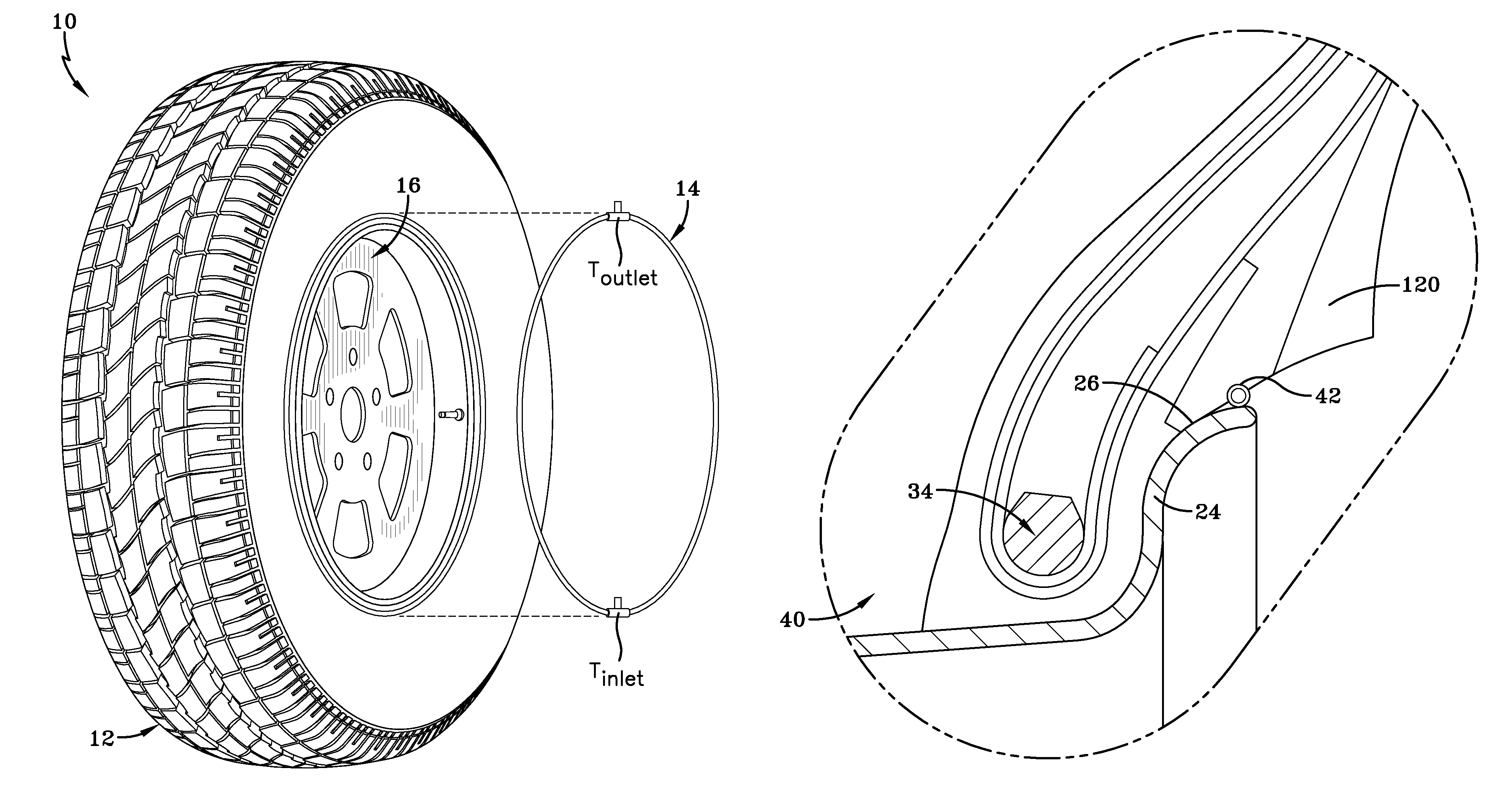
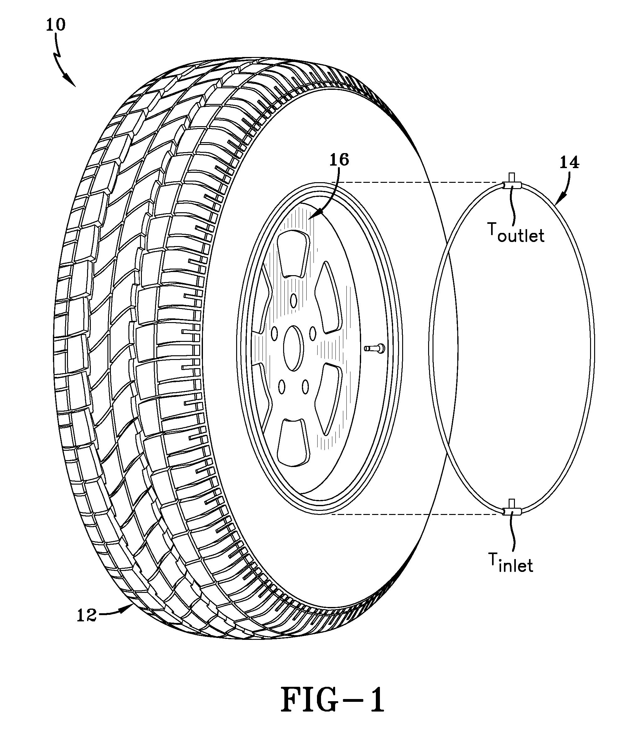
[0040]Referring to FIGS. 1 and 5, a tire assembly 10 includes a tire 12, a peristaltic pump assembly 14, and a tire wheel 16. The tire mounts in conventional fashion to a pair of rim mounting surfaces 18, 20 adjacent outer rim flanges 22, 24. The rim flanges 22, 24, have radially outward facing surface 26. A rim body 28 supports the tire assembly as shown. The tire is of conventional construction, having a pair of sidewalls 30, 32 extending from opposite bead areas 34, 36 to a crown or tire read region 38. The tire and rim enclose a tire cavity 40.

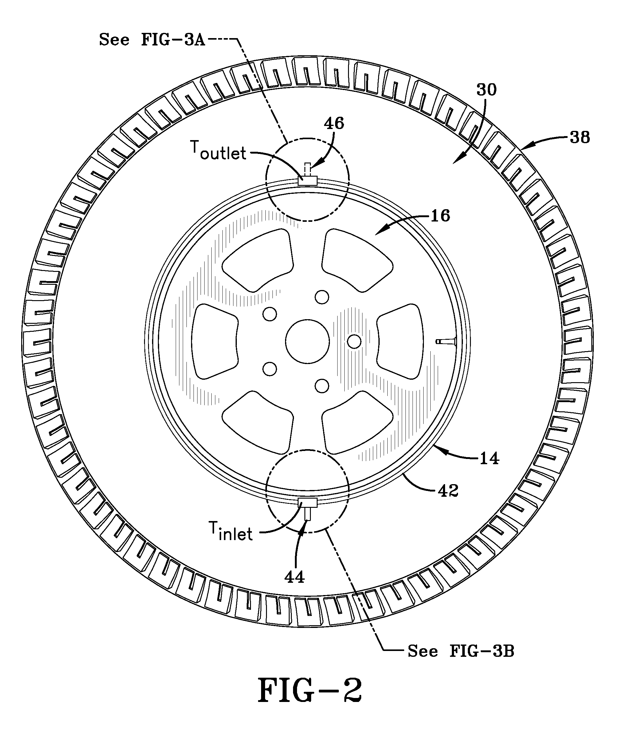
[0041]As seen from FIGS. 2 and 3A, B, and C, the peristaltic pump assembly 14 includes an annular air tube 42 that encloses an annular passageway 43. The tube 42 is formed of a resilient, flexible material such as plastic or rubber compounds that is capable of withstanding repeated deformation cycles wherein the tube is deformed into a flattened condition subject to external force and, upon removal of such force, returns to an original con...


PUM


Abstract

A self-inflating tire assembly includes an annular air tube connected to a tire and defining an annular air passageway, the air tube being composed of a flexible material operative to allow an air tube segment opposite a tire footprint to flatten, closing the passageway, and resiliently unflatten into an original configuration. The air tube is sequentially flattened by the tire footprint in a direction opposite to a tire direction of rotation to pump air along the passageway to an inlet device for exhaust from the passageway or to an outlet device for direction into the tire cavity. The inlet device is positioned within the annular passageway 180 degrees opposite the outlet device such that sequential flattening of the air tube by the tire footprint effects pumping of air along the air passageway with the tire rotating in either a forward or reverse direction of rotation.

Description

FIELD OF THE INVENTION[0001]The invention relates generally to self-inflating tires and, more specifically, to a pump mechanism for such tires.BACKGROUND OF THE INVENTION[0002]Normal air diffusion reduces tire pressure over time. The natural state of tires is under inflated. Accordingly, drivers must repeatedly act to maintain tire pressures or they will see reduced fuel economy, tire life and reduced vehicle braking and handling performance. Tire Pressure Monitoring Systems have been proposed to warn drivers when tire pressure is significantly low. Such systems, however, remain dependant upon the driver taking remedial action when warned to re-inflate a tire to recommended pressure. It is a desirable, therefore, to incorporate a self-inflating feature within a tire that will self-inflate the tire in order to compensate for any reduction in tire pressure over time without the need for driver intervention.SUMMARY OF THE INVENTION[0003]In one aspect of the invention, a self-inflating ...

Claims


Application Information

Patent Timeline
Patent Type & Authority Patents(United States)
IPC IPC(8): B60C25/00
CPCB60C23/12B60C23/123B60C23/135B60C23/10B60C2019/008
Inventor BENEDICT, ROBERT LEON
Owner THE GOODYEAR TIRE & RUBBER CO
Why Eureka
Try Eureka