Collapsible hook hanger

a hook and collapsible technology, applied in the field of garment hangers, can solve the problem of entanglement and additional shipping costs, and achieve the effect of reducing the footprin

Active Publication Date: 2012-02-14
SOURCING SOLUTIONS INT
View PDF27 Cites 28 Cited by
  • Summary
  • Abstract
  • Description
  • Claims
  • Application Information

AI Technical Summary

Benefits of technology

[0008]As a result, the present invention provides a garment hanger which functions and operates as a conventional garment hanger in a retail location, but is designed to allow the hook to move between an upright position and a folded position whereupon the folded position provides a reduced footprint during packaging / transportation of pre-hung garments.

Problems solved by technology

This additional space, of course, translates into additional shipping costs.

Method used


Image

  • Collapsible hook hanger
  • Collapsible hook hanger
  • Collapsible hook hanger

Examples


Embodiment Construction

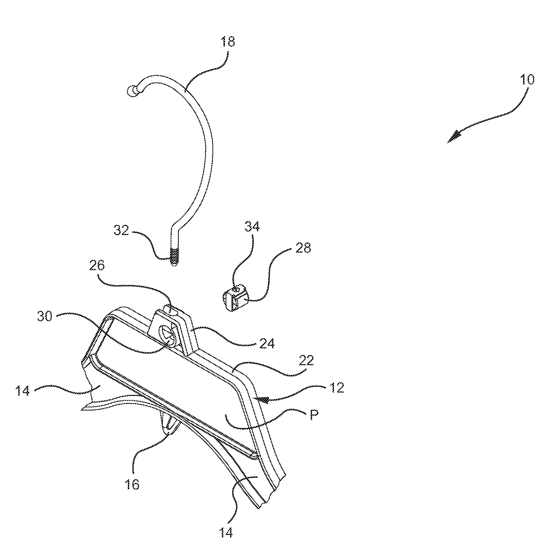
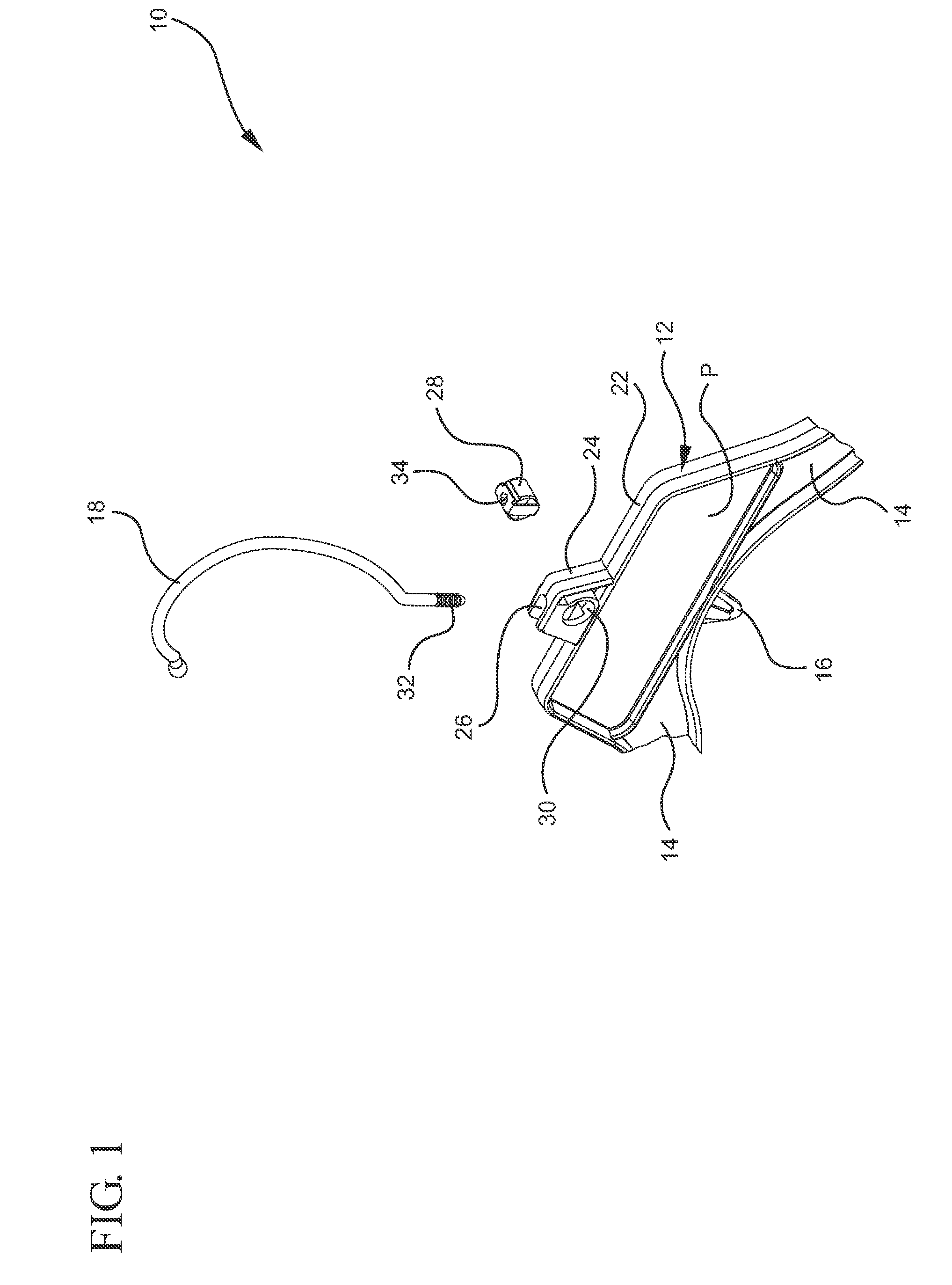
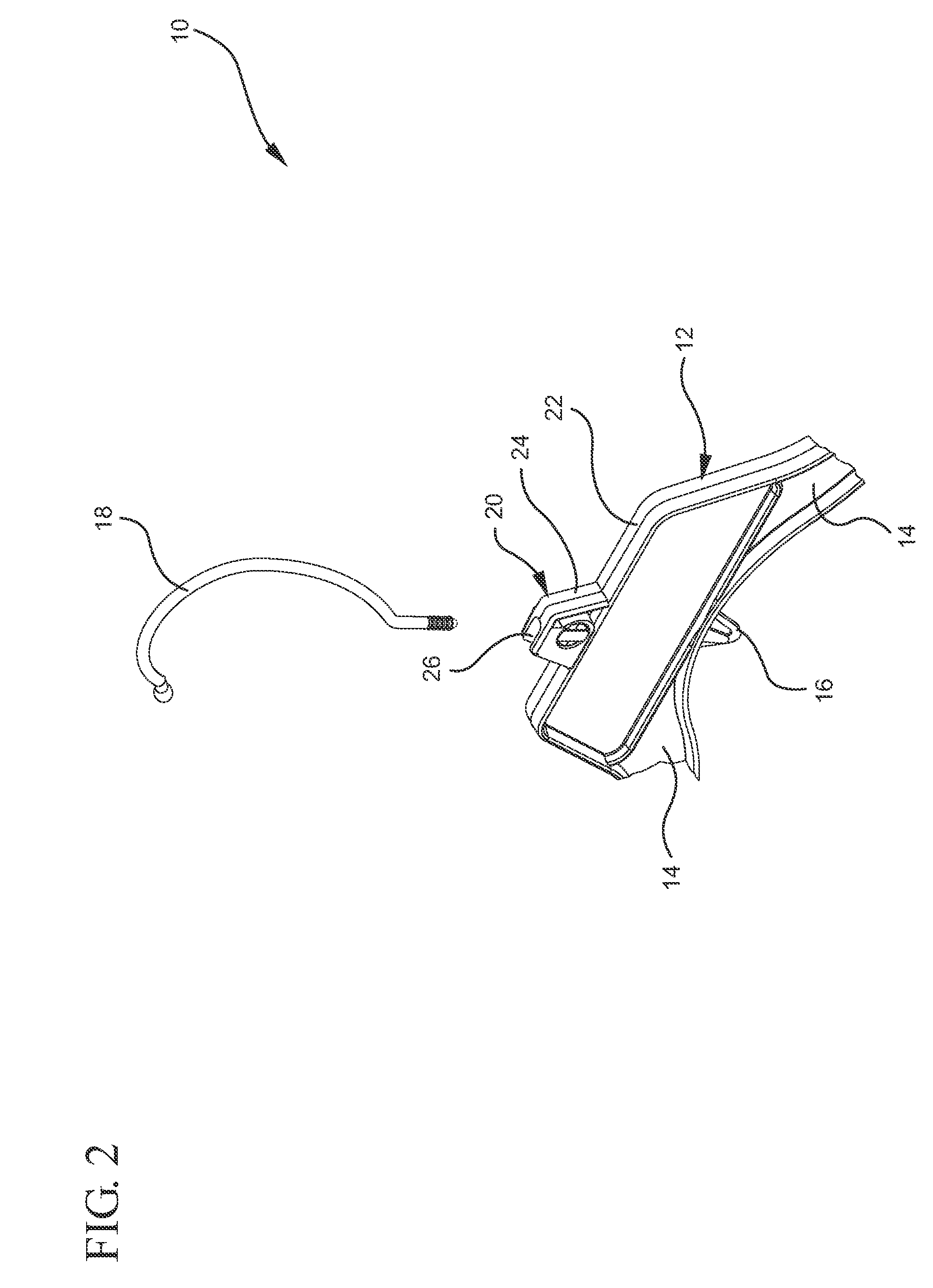
[0029]Hanger 10, formed in accordance with the present invention, is shown in FIGS. 1-9. Hanger 10 includes a central body portion 12 defining a plane P, and a pair of opposing downwardly-depending arms 14. In one preferred embodiment, hanger 10 is formed with an I-beam construction. In another preferred embodiment, hanger 10 includes a coordinate loop 16 for receiving the hook of a second hanger (not shown).

[0030]Hanger 10 includes a metal hook 18, which is shown in an upright position in FIG. 3 and in a folded position in FIG. 5. More particularly, hook 18 is rotatable between these two positions. When the hook is in the upright position, hanger 10 functions as a conventional garment hanger for supporting and displaying a garment. However, during transportation / shipping, hook 18 can be moved to the folded position to reduce the footprint of the hanger, and thus the overall size of the shipping box / container into which the garments are loaded. The reduction in size of the shipping ...


PUM


Abstract

A collapsible hook hanger having a metal hook moveable between an upright position for displaying garments and a folded position for reducing the footprint of the hanger during packaging / transportation of pre-hung garments.

Description

[0001]This application claims the benefit of U.S. Provisional Application Ser. No. 61 / 122,598 filed Dec. 15, 2008 and U.S. Provisional Application Ser. No. 61 / 042,990 filed Apr. 7, 2008, the disclosures of which are hereby incorporated by reference in their entirety.BACKGROUND OF THE INVENTION[0002]The present invention relates to garment hangers and, more particularly, to garment hanger having a collapsible hook.[0003]Garment hangers featuring metal hooks are well-known in the art. These hangers typically include a threaded boss located on the upper frame, the threaded boss receiving a threaded end of the metal hook. The body of the hanger is typically made of plastic.[0004]Many garments that are manufactured oversees are pre-hung on a hanger, and then shipped to the United States as a hanger / garment combination. In other words, the garment is hung on the appropriate hanger at the manufacturing location (e.g., the Far East), packaged into a shipping box or container, and shipped to...

Claims


Application Information

Patent Timeline
Patent Type & Authority Patents(United States)
IPC IPC(8): A41D27/22
CPCA47G25/32A47G25/1428A47G25/183Y10S223/04
Inventor HO, LEUNG
Owner SOURCING SOLUTIONS INT
Why Eureka
Try Eureka