Coverage antenna apparatus with selectable horizontal and vertical polarization elements

a technology of horizontal and vertical polarization elements and antenna apparatuses, applied in the field of wireless communication, can solve the problems of reducing affecting the service life of antennas, so as to reduce the footprint of slot antennas

Active Publication Date: 2008-04-15
ARRIS ENTERPRISES LLC
View PDF144 Cites 105 Cited by
  • Summary
  • Abstract
  • Description
  • Claims
  • Application Information

AI Technical Summary

Benefits of technology

[0016]In one aspect, a system comprises a housing, a communication device, and an antenna apparatus including one or more slot antennas integral with the housing. One or more of the slot antennas may comprise loading elements configured to decrease a footprint of the slot antenna. One or more of the slot antennas may comprise an aperture formed in the housing.

Problems solved by technology

The wireless link may be susceptible to interference from other access points and stations, other radio transmitting devices, changes or disturbances in the wireless link environment between the access point and the remote receiving node, and so on.
The interference may be such to degrade the wireless link, for example by forcing communication at a lower data rate, or may be sufficiently strong to completely disrupt the wireless link.
However, one problem with using two or more omnidirectional antennas for the access point is that typical omnidirectional antennas are vertically polarized.
Vertically polarized radio frequency (RF) energy does not travel as efficiently as horizontally polarized RF energy inside a typical office or dwelling space.
Typical horizontally polarized RF antennas to date have been expensive to manufacture, or do not provide adequate RF performance to be commercially successful.
A further problem is that the omnidirectional antenna typically comprises an upright wand attached to a housing of the access point.
The wand typically comprises a hollow metallic rod exposed outside of the housing, and may be subject to breakage or damage.
Another problem is that each omnidirectional antenna comprises a separate unit of manufacture with respect to the access point, thus requiring extra manufacturing steps to include the omnidirectional antennas in the access point.
Yet another problem is that the access point with the typical omnidirectional antennas is a relatively large physically, because the omnidirectional antennas extend from the housing.
A still further problem with the two or more omnidirectional antennas is that because the physically separated antennas may still be relatively close to each other, each of the several antennas may experience similar levels of interference and only a relatively small reduction in interference may be gained by switching from one omnidirectional antenna to another omnidirectional antenna.
However, the phased array antenna can be extremely expensive to manufacture.
Further, the phased array antenna can require many phase tuning elements that may drift or otherwise become maladjusted.

Method used


Image

  • Coverage antenna apparatus with selectable horizontal and vertical polarization elements
  • Coverage antenna apparatus with selectable horizontal and vertical polarization elements
  • Coverage antenna apparatus with selectable horizontal and vertical polarization elements

Examples


Embodiment Construction

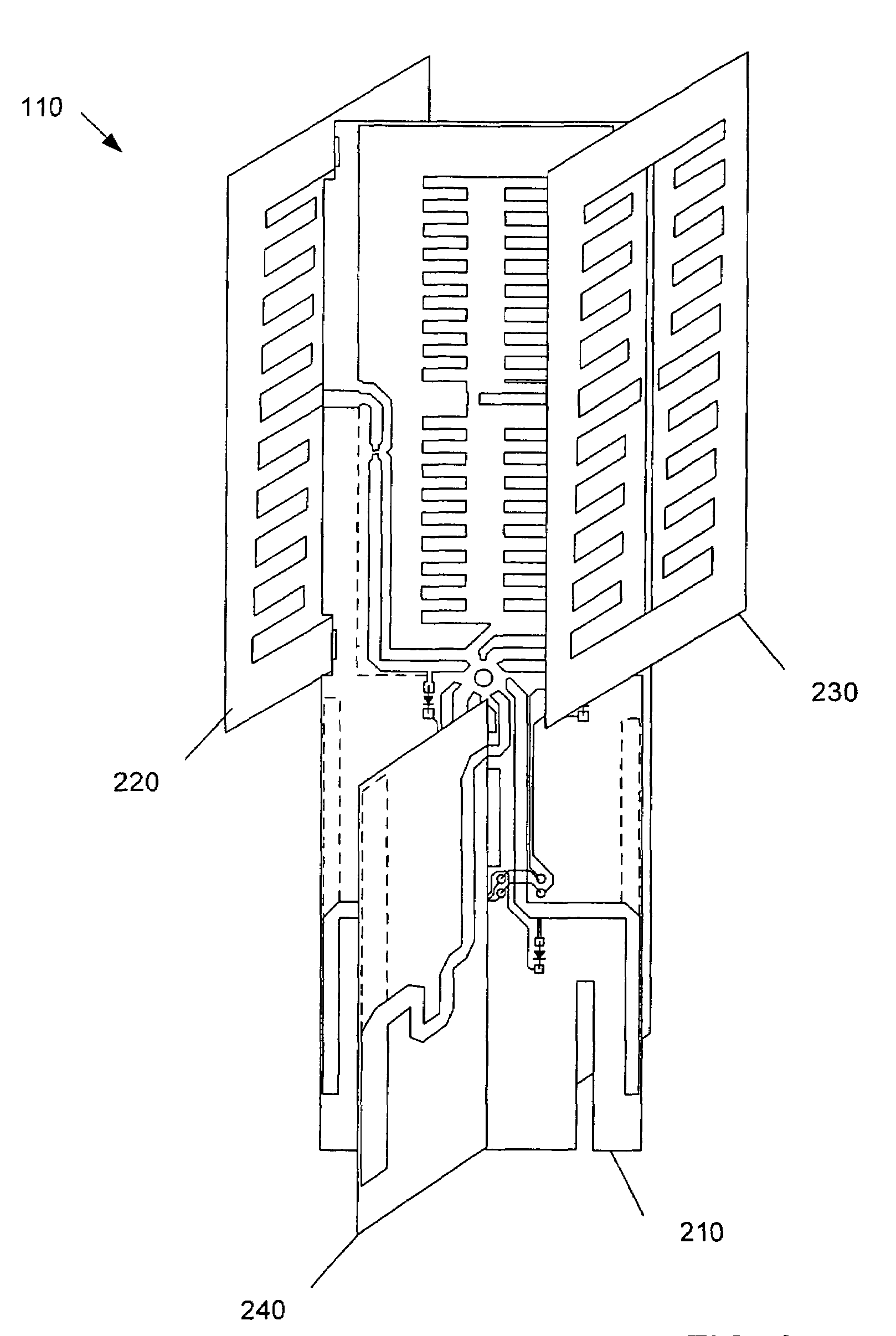
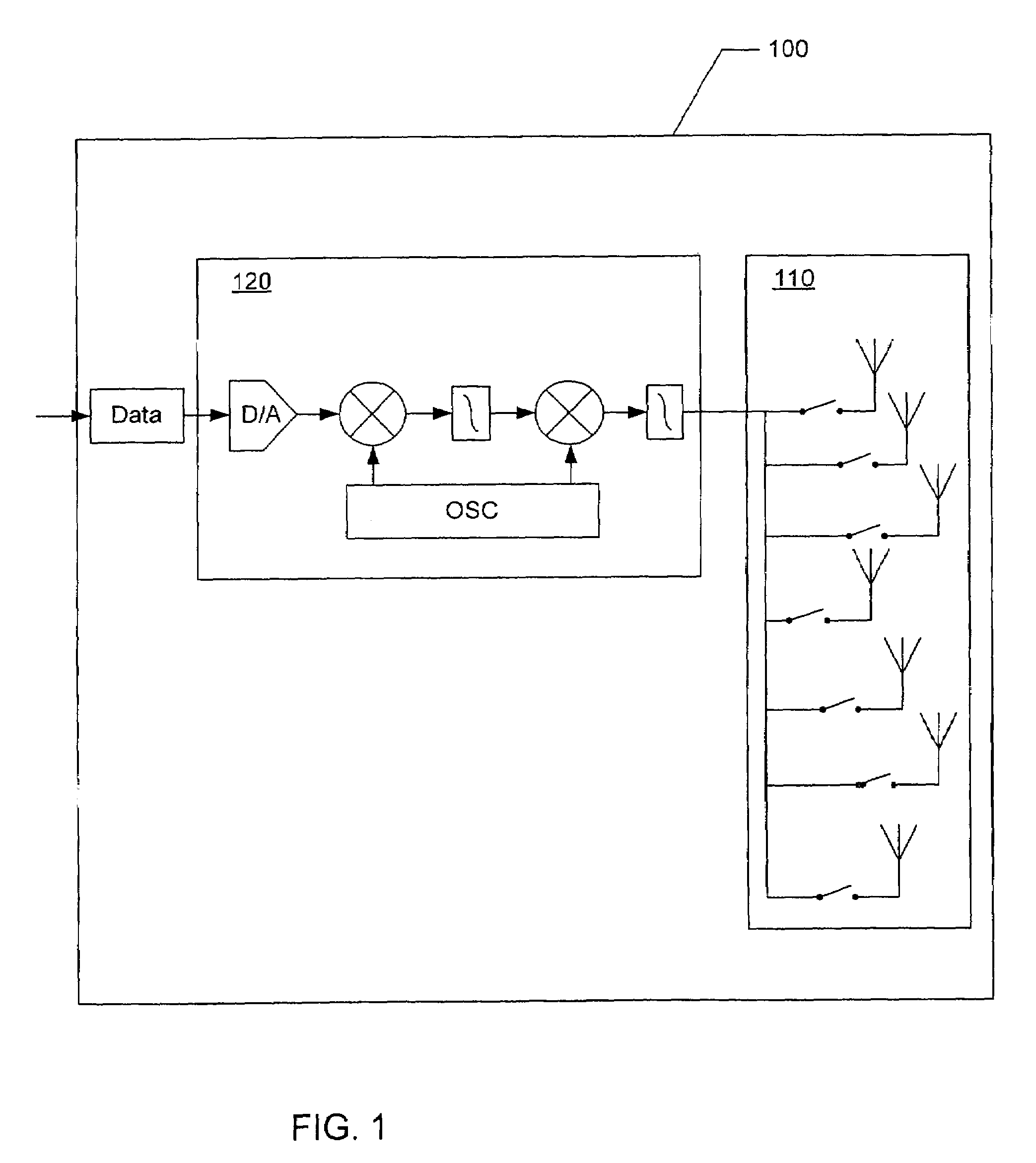
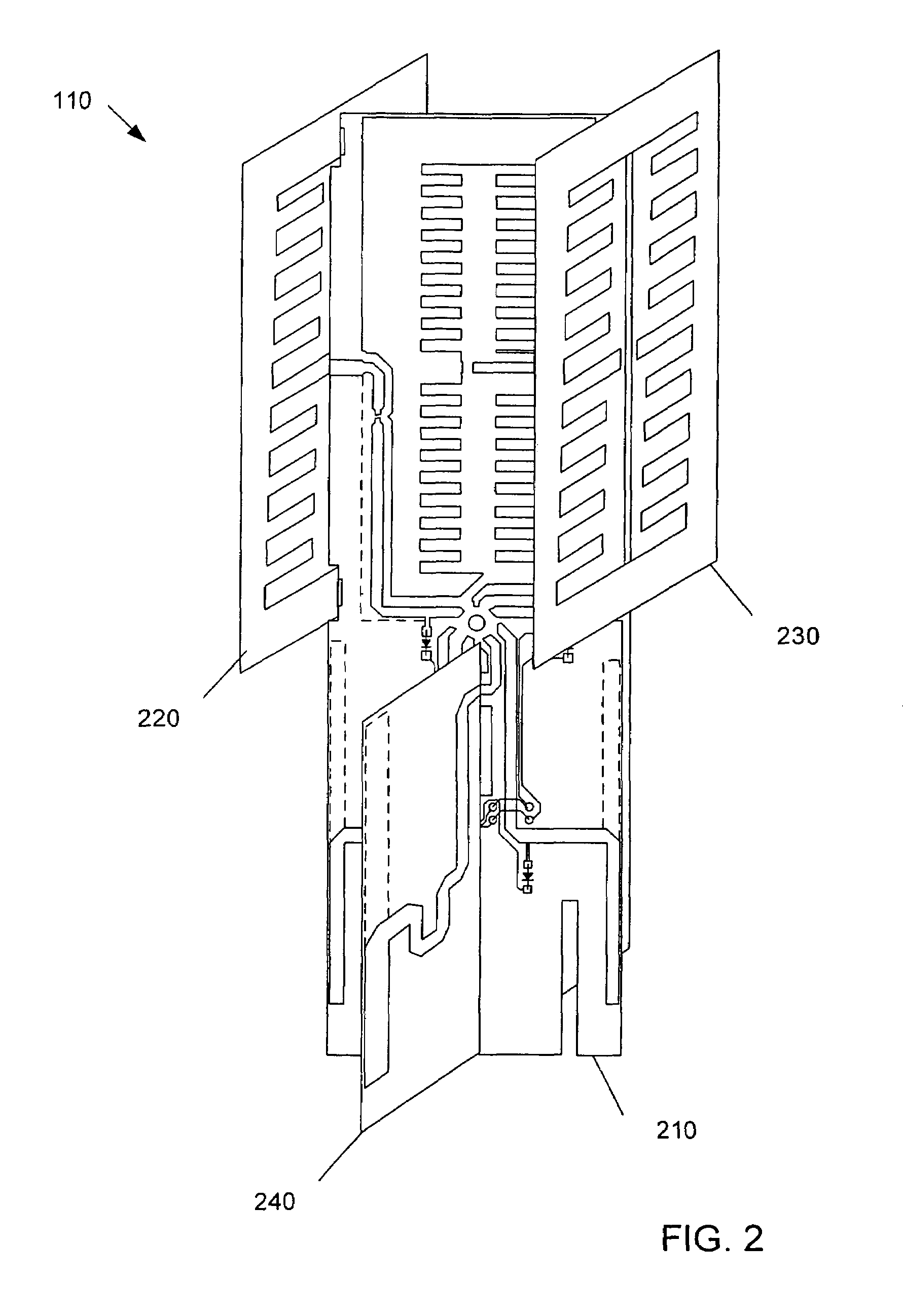
[0025]A system for a wireless (i.e., radio frequency or RF) link to a remote receiving node includes a communication device for generating an RF signal and an antenna apparatus for transmitting and / or receiving the RF signal. The antenna apparatus comprises a plurality of modified dipoles (also referred to herein as simply “dipoles”) and / or a plurality of modified slot antennas (also referred to herein as simply “slots”). In a preferred embodiment, the antenna apparatus includes a number of slots configured to transmit and / or receive horizontal polarization, and a number of dipoles to provide vertical polarization. Each dipole and each slot provides gain (with respect to isotropic) and a polarized directional radiation pattern. The slots and the dipoles may be arranged with respect to each other to provide offset radiation patterns.

[0026]In some embodiments, the dipoles and the slots comprise individually selectable antenna elements and each antenna element may be electrically selec...


PUM


Abstract

An antenna apparatus comprises selectable antenna elements including a plurality of dipoles and/or a plurality of slot antennas (“slot”). Each dipole and/or each slot provides gain with respect to isotropic. The dipoles may generate vertically polarized radiation and the slots may generate horizontally polarized radiation. Each antenna element may have one or more loading structures configured to decrease the footprint (i.e., the physical dimension) of the antenna element and minimize the size of the antenna apparatus.

Description

CROSS-REFERENCE TO RELATED APPLICATIONS[0001]This application claims the priority benefit of U.S. provisional patent application No. 60 / 694,101 filed Jun. 24, 2005, the disclosure of which is incorporated herein by reference. This application is related to and incorporates by reference co-pending U.S. application Ser. No. 11 / 041,145 titled “System and Method for a Minimized Antenna Apparatus with Selectable Elements” filed Jan. 21, 2005; U.S. application Ser. No. 11 / 022,080 titled “Circuit Board having a Peripheral Antenna Apparatus with Selectable Antenna Elements” filed Dec. 23, 2004; U.S. application Ser. No. 11 / 010,076 titled “System and Method for Omnidirectional Planar Antenna Apparatus with Selectable Elements” filed Dec. 9, 2004; U.S. application Ser. No. 11 / 180,329 titled “System and Method for Transmission Parameter Control for an Antenna Apparatus with Selectable Elements” filed Jul. 12, 2005; and U.S. application Ser. No. 11 / 190,288 titled “Wireless System Having Multipl...

Claims


Application Information

Patent Timeline
Patent Type & Authority Patents(United States)
IPC IPC(8): H01Q21/00
CPCH01Q3/242H01Q9/16H01Q21/245H01Q21/205H01Q13/10
Inventor KISH, WILLIAMSHTROM, VICTOR
Owner ARRIS ENTERPRISES LLC
Why Eureka
Try Eureka