Protective electrical wiring device with light

a technology of electrical wiring and light, which is applied in the direction of switching devices operated by earth fault currents, switch condition indication, electrical equipment, etc., can solve the problems of failure modes, normal aging of electronic components, and failure of wiring devices having circuit protection devices

Active Publication Date: 2012-02-21
PASS SEYMOUR
View PDF8 Cites 20 Cited by
  • Summary
  • Abstract
  • Description
  • Claims
  • Application Information

AI Technical Summary

Problems solved by technology

In certain environments where a greater potential for an electrical shock hazard may exist, such as in a residential bathroom or kitchen, for example, the wiring device may be equipped with a circuit protection device component, e.g., a ground fault circuit interrupter (GFCI) (however, the use of wiring devices having a circuit protection device component or capability is in no way limited to these exemplary environments).
Since the protective device component includes both electronic and mechanical components, failure modes may result from normal aging of electronic components, corrosion of mechanical parts, poor connections, mechanical wear, mechanical or overload abuse of the protective device in the field, electrical disturbances such as from lightning, or the like.

Method used


Image

  • Protective electrical wiring device with light
  • Protective electrical wiring device with light
  • Protective electrical wiring device with light

Examples


Embodiment Construction

[0039]Reference will now be made in detail to the present exemplary embodiments of the invention, examples of which are illustrated in the accompanying drawings. Wherever possible, the same reference numbers will be used throughout the drawings to refer to the same or like parts. An exemplary embodiment of the electrical wiring device of the present invention is shown in FIG. 1, and is designated generally throughout by reference numeral 10.

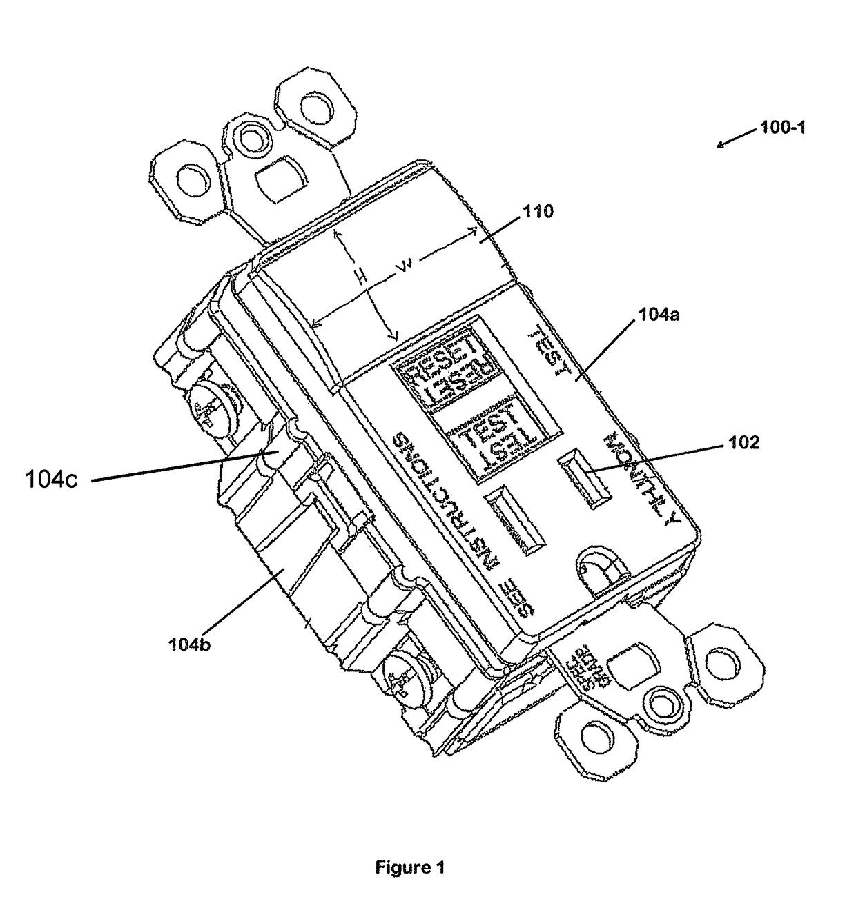
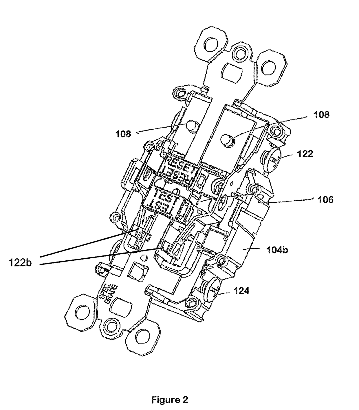
[0040]An embodiment according to the invention is now described with initial reference to FIGS. 1 and 2. FIG. 1 shows an assembled perspective illustration of an exemplary electrical wiring device 100-1 having grounded receptacle openings 102. The electrical wiring device 100-1 includes a housing 104 having a face portion 104a, a back portion 104b, and a separator portion 104c disposed therebetween. Receptacle openings 102 are formed in the face / cover portion 104a. Line terminals 124 are disposed in the back portion 104b of the housing 104 undern...


PUM


Abstract

The present invention is directed to an electrical wiring device that includes an illumination assembly coupled to at least one detection circuit and disposed in the housing portion. The illumination assembly includes at least one light emitting element, an illumination circuit, and at least one lens disposed in at least one lens cover opening in optical communication with at least one light emitting element. The illumination circuit is configured to selectively drive the at least one light emitting element between a deenergized state and a light emitting state in response to an ambient light condition, a miswire condition, an end-of-life condition, a reset state or a trip state. The at least one lens has a surface area such that light emitted by the at least one light emitting element is directed into a spatial volume proximate the electrical wiring device.

Description

CROSS-REFERENCE TO RELATED APPLICATIONS[0001]This is a continuation of U.S. patent application Ser. No. 10 / 998,369 filed on Nov. 29, 2004, the content of which is relied upon and incorporated herein by reference in its entirety, and the benefit of priority under 35 U.S.C. §120 is hereby claimed. U.S. patent application Ser. No. 10 / 998,369 claims the benefit of priority under 35 U.S.C. §119(e) to U.S. provisional application Ser. No. 60 / 550,275 filed on Mar. 5, 2004, which is incorporated herein by reference in its entirety.BACKGROUND OF THE INVENTION[0002]1. Field of the Invention[0003]The present invention relates generally to electrical wiring devices, and particularly to electrical wiring devices including protective circuitry.[0004]2. Technical Background[0005]Electrical wiring devices often include power receptacles that may receive a corded plug to thereby supply power to electrical equipment connected to the plug. In certain environments where a greater potential for an elect...

Claims


Application Information

Patent Timeline
Patent Type & Authority Patents(United States)
IPC IPC(8): H02H3/00
CPCH01H71/04H01H83/04
Inventor RADOSAVLJEVIC, DEJANVOUGHT, KENNETH D.SAVICKI, JR., GERALD R.WEEKS, RICHARDWILSON, GARY O.
Owner PASS SEYMOUR
Why Eureka
Try Eureka