
Guiding and taxiing assistance optoelectronic device for an aircraft having a dedicated symbology

a technology of optoelectronic devices and aircraft, which is applied in the direction of navigation instruments, instruments, process and machine control, etc., can solve the problems of large distance between main landing gear and nose wheel, insufficient representation, and insufficient maneuverability

Active Publication Date: 2012-02-28
THALES SA
View PDF13 Cites 10 Cited by
  • Summary
  • Abstract
  • Description
  • Claims
  • Application Information

AI Technical Summary

Benefits of technology

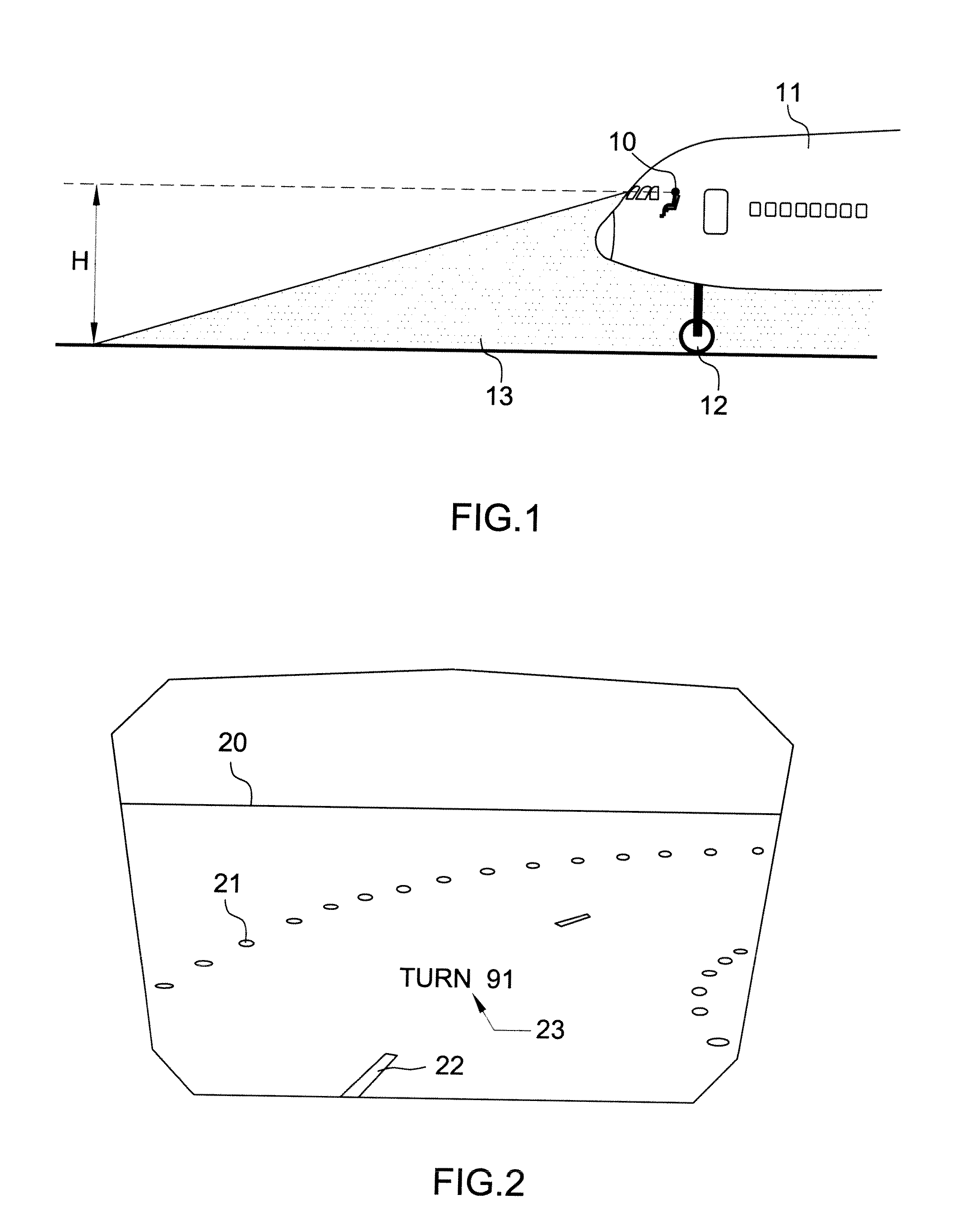
The invention is a device that helps pilots guide their aircraft on airport traffic ways. It uses a head-up display to show the pilot the deviation of their actual trajectory from the theoretical trajectory. This allows the pilot to anticipate changes in trajectory and maintain a safe distance from other aircraft. The device calculates a deviation factor based on the first angle between the points of the landing gear and the guidance point, and generates symbols that are displayed on the landscape. The pilot can control the device either mechanically or digitally, and the anticipation information is displayed as a blinking symbol. The invention makes it easier for pilots to maintain safe distances from other aircraft and ensures safe taxiing.

Problems solved by technology

Aircraft landing gear often has a significant footprint and occupies an appreciable part of the width of the traffic ways.
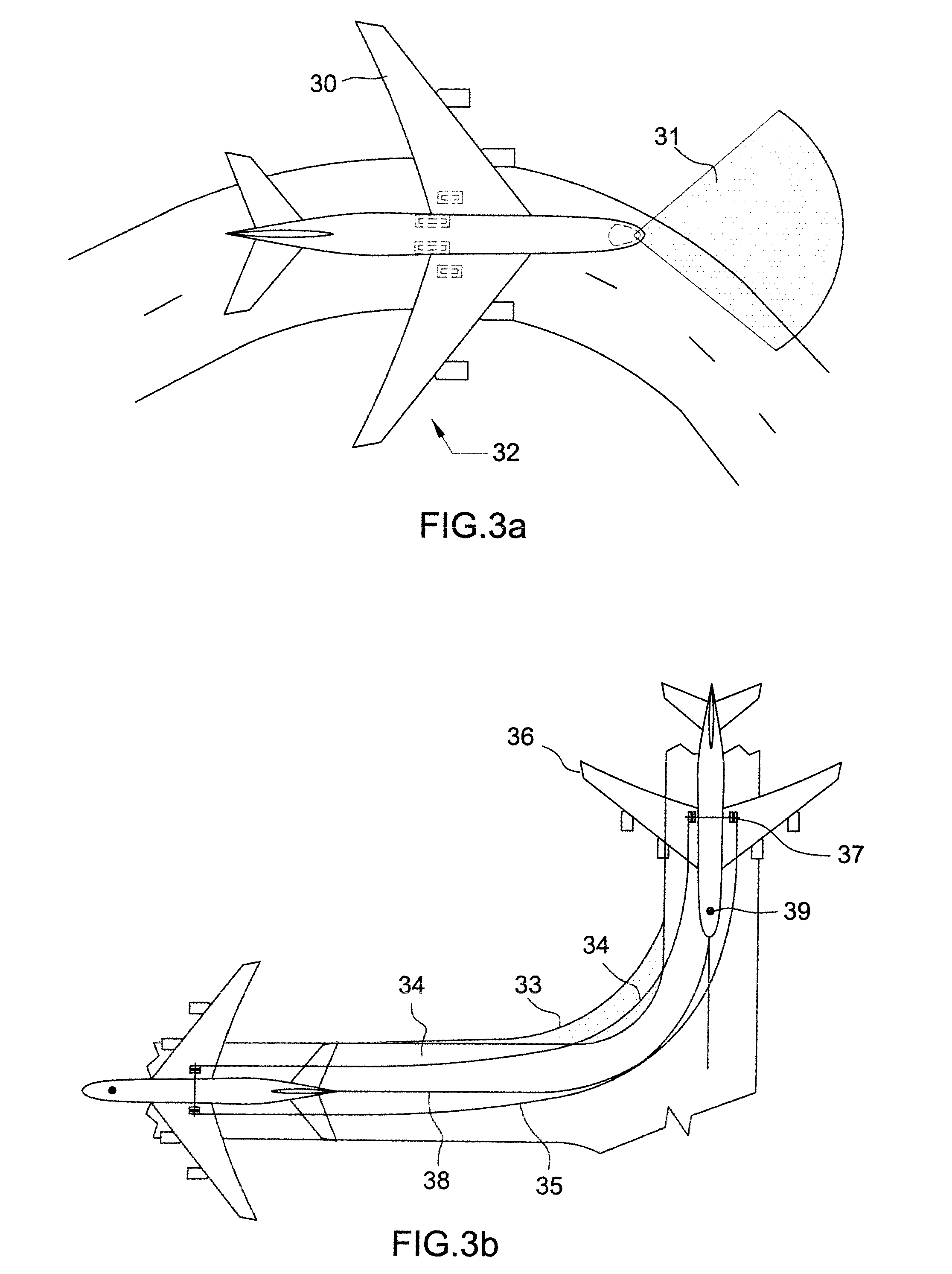
One of the tricky points of taxiing is the negotiating of turns.
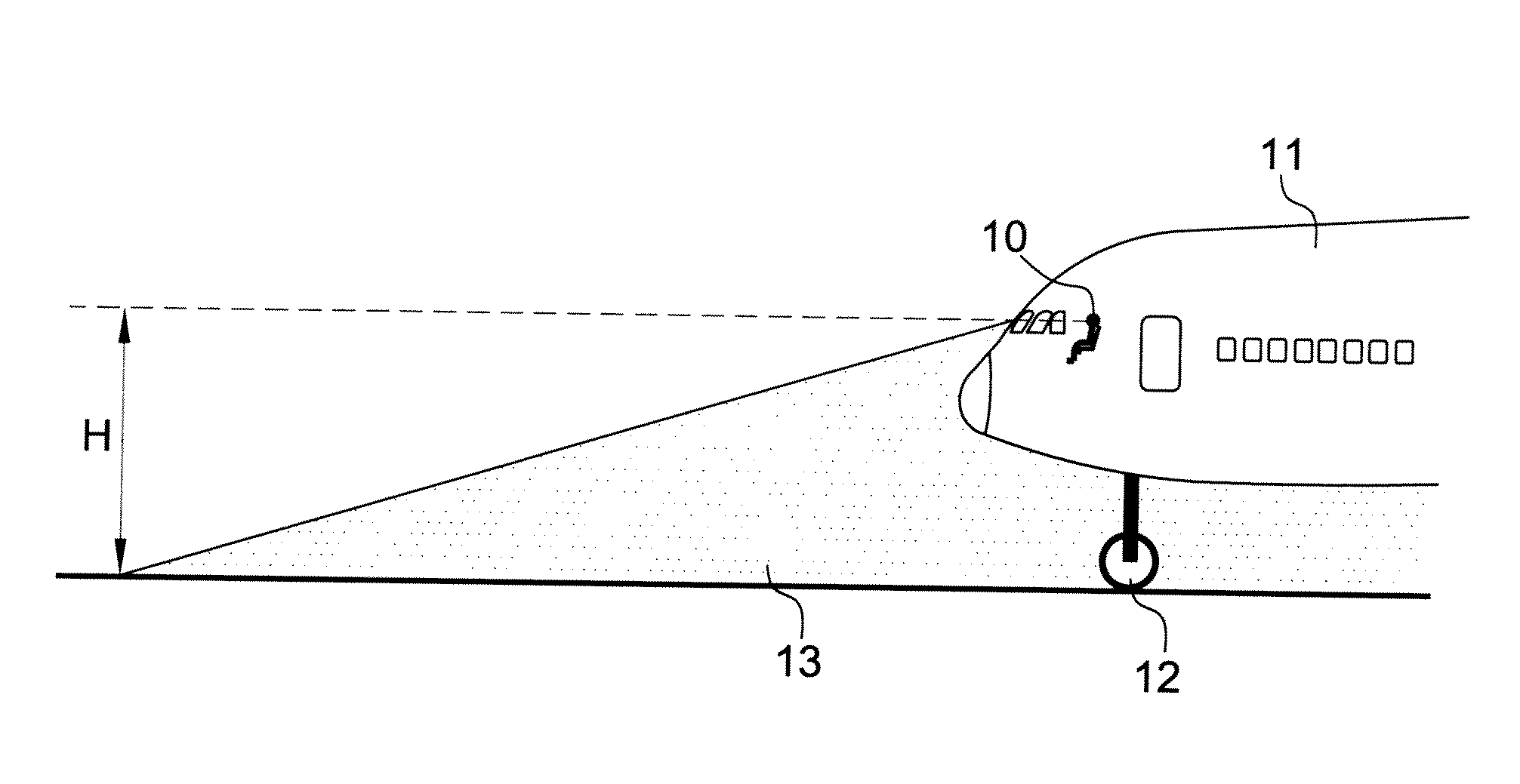
Moreover, the large distance separating the main landing gear and the nose wheel 12 does not facilitate maneuvers.
However, when the craft is in the middle of a turn, this representation becomes insufficient.
Nevertheless, content of the pilot's restricted field in aircraft of the A380 type, or equivalent wide-body craft, and of the severe climatic conditions which may be detrimental to visibility, notably in turns, the pilot does not always have a simple criterion relating to the deviation of his actual trajectory with respect to the theoretical trajectory that he ought to follow.

Method used


Image

  • Guiding and taxiing assistance optoelectronic device for an aircraft having a dedicated symbology
  • Guiding and taxiing assistance optoelectronic device for an aircraft having a dedicated symbology
  • Guiding and taxiing assistance optoelectronic device for an aircraft having a dedicated symbology

Examples


Embodiment Construction

[0066]The objective of the device according to the invention is to determine a simple criterion for the deviation between the trajectory followed by the aircraft and the theoretical trajectory. The theoretical trajectory is defined by the curve centered on the runway.

[0067]The definition of a reference point, called the guidance point in what follows, situated on the main axis of the aircraft is required by the pilot so that the latter taxis constantly over the runway. For example, for medium-size aircraft, of A320 type, the guidance point can be the nose wheel, the latter being the aircraft's most advanced wheel. In this case, the pilot guides the aircraft on the airport traffic ways, in such a way that the nose wheel remains constantly above the middle of the runway.

[0068]The device according to the invention consists in providing the pilot with a symbology representing, in this example, the deviation between the nose wheel and the center of the runway.

[0069]Having regard to the r...


PUM


Abstract

The invention pertains to optoelectronic devices for aiding the guidance and taxiing of aircraft, comprising a so-called head-up collimator allowing the presentation of information in the pilot's visual field. It applies notably to large-size civil aircraft of the Boeing 747 or Airbus A380 type. The optoelectronic device comprises means for calculating a deviation factor for the actual trajectory of said aircraft relative to a theoretical trajectory on said traffic way, means for generating symbols and at least one head-up collimator comprising means for displaying and superimposing said symbols on the outside landscape. The deviation factor is calculated on the basis of an angle (PÂ′G) and that the means for generating symbols generate a symbol representing said deviation factor, so as to be superimposed on said traffic way.

Description

CROSS-REFERENCE TO RELATED APPLICATIONS[0001]The present Application is based on International Application No. PCT / EP2007 / 060722, filed on Oct. 9, 2007, which in turn corresponds to French Application No. 0608869, filed on Oct. 10, 2006, and priority is hereby claimed under 35 USC §119 based on these applications. Each of these applications are hereby incorporated by reference in their entirety into the present application.TECHNICAL FIELD[0002]The invention pertains to optoelectronic devices for aiding the guidance and taxiing of aircraft, comprising a so-called head-up collimator allowing the presentation of information in the pilot's visual field. It applies notably to large-size civil aircraft of the Boeing 747 or Airbus A380 type.BACKGROUND OF THE INVENTION[0003]It is important that aircraft ground taxiing phases in an airport can take place in complete safety, whatever the density of the air traffic or the visibility conditions. Aircraft landing gear often has a significant foo...

Claims


Application Information

Patent Timeline
Patent Type & Authority Patents(United States)
IPC IPC(8): G01C21/00
CPCG01C23/005G08G5/0086
Inventor DUBOURG, BERNARDMICHEL, FRANCOIS
Owner THALES SA
Learn More