Gear change arrangement and a gearbox

a technology of gearboxes and control devices, which is applied in the direction of mechanical control devices, process and machine control, instruments, etc., can solve the problem of low manufacturing cos

Inactive Publication Date: 2012-03-06
SCANIA CV AB
View PDF11 Cites 1 Cited by
  • Summary
  • Abstract
  • Description
  • Claims
  • Application Information

AI Technical Summary

Benefits of technology

[0007]The locking in device being mounted on or forming part of a wire spring which provides the necessary spring force for the locking arrangement makes it possible for the locking arrangement to have a simple and space-saving configuration comprising relatively few components, resulting inter alia in the possibility of low manufacturing costs.
[0008]According to a preferred embodiment of the invention, the locking device takes the form of a roller mounted for rotation on the wire spring, resulting in low friction and little wear between the locking device and the control rod.

Problems solved by technology

The locking in device being mounted on or forming part of a wire spring which provides the necessary spring force for the locking arrangement makes it possible for the locking arrangement to have a simple and space-saving configuration comprising relatively few components, resulting inter alia in the possibility of low manufacturing costs.

Method used


Image

  • Gear change arrangement and a gearbox
  • Gear change arrangement and a gearbox
  • Gear change arrangement and a gearbox

Examples


Embodiment Construction

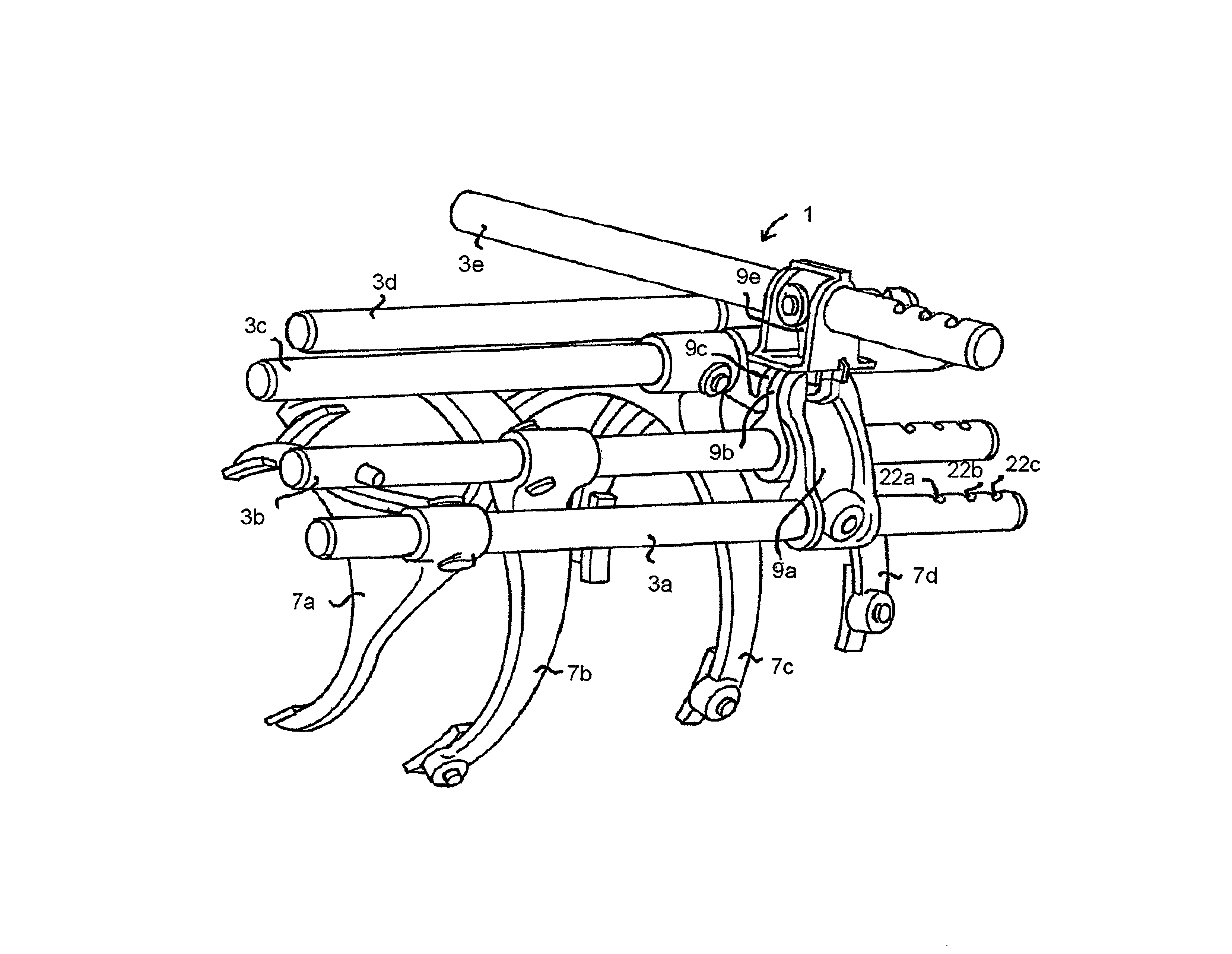
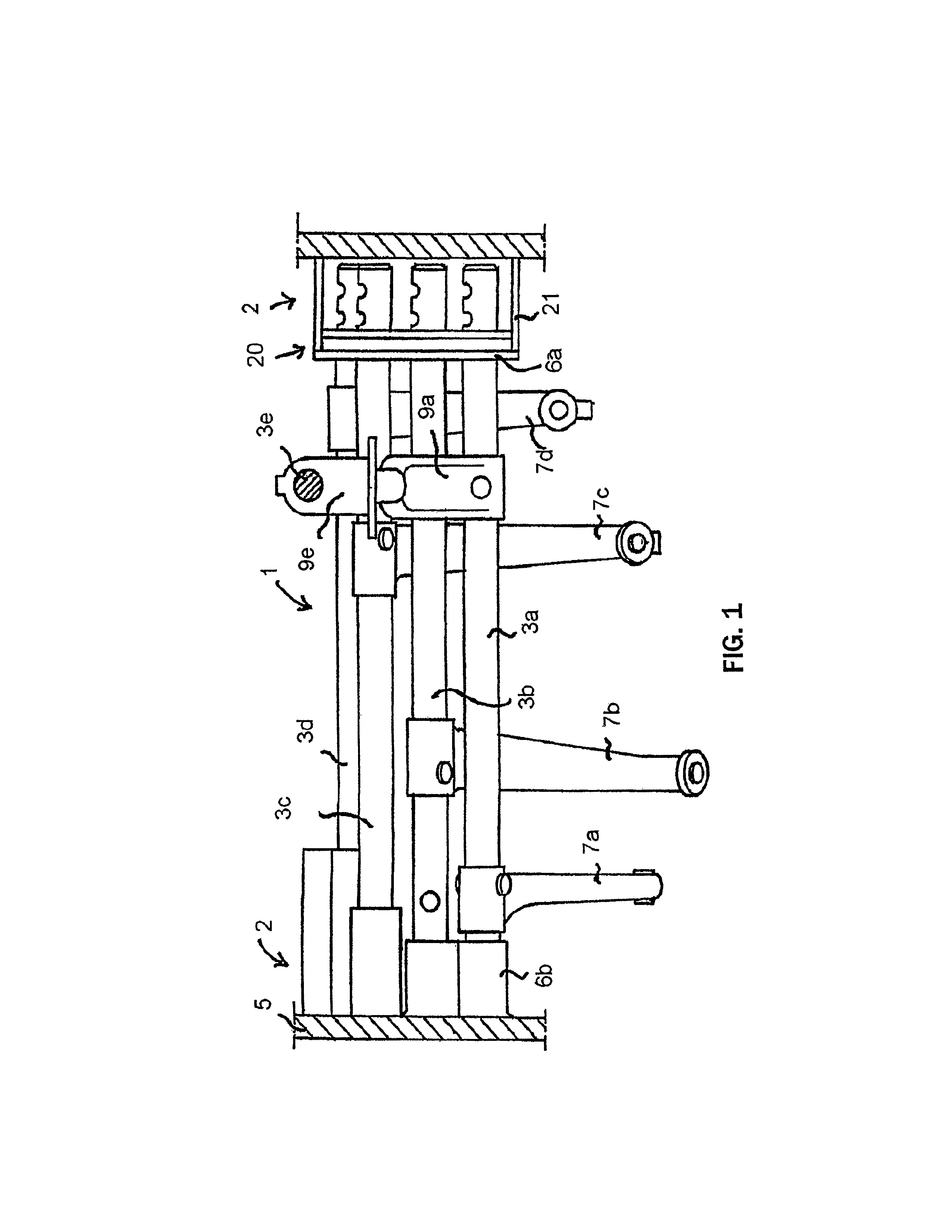
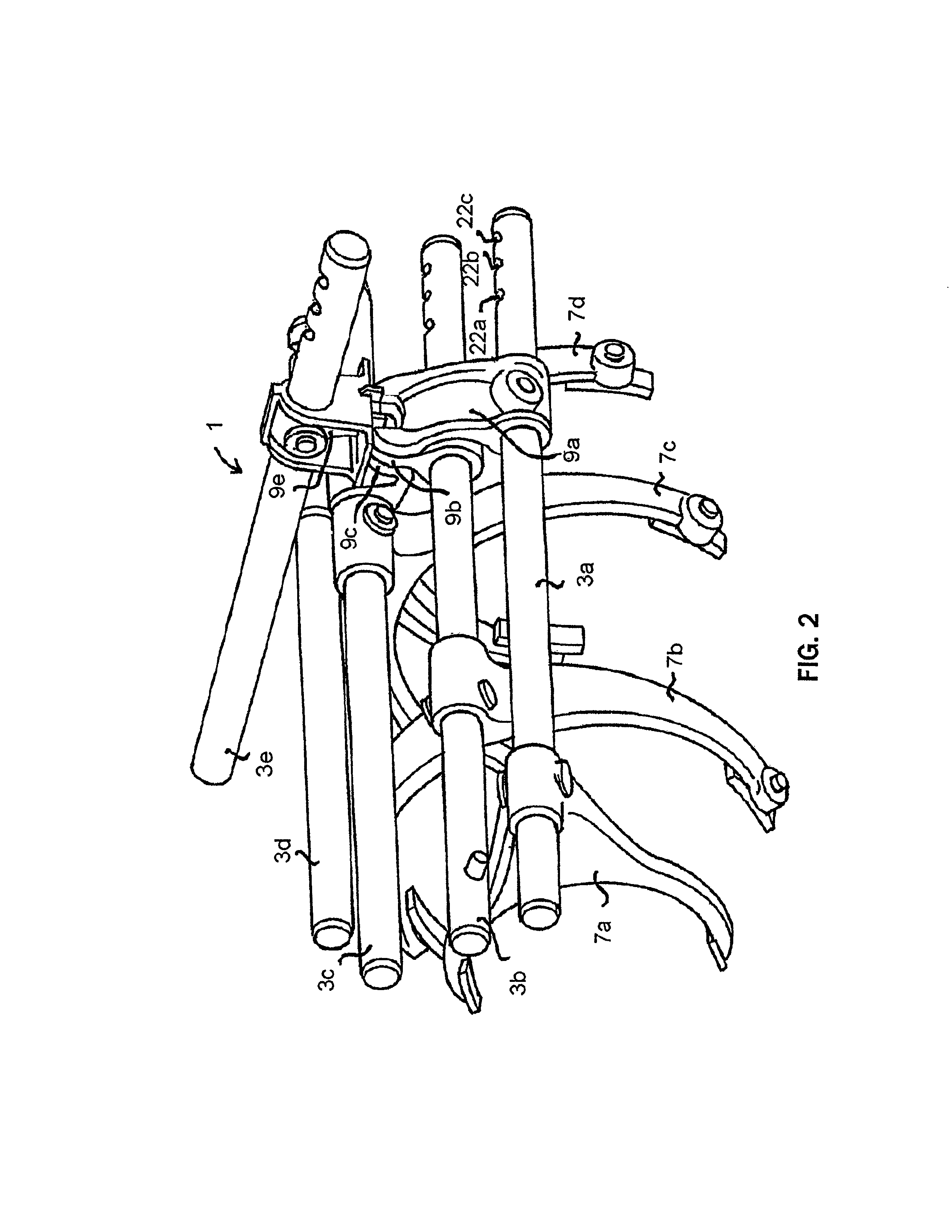
[0024]The control device 1 according to the invention is intended to form part of a gearbox in order to control the engagement of desired gears of the gearbox. Apart from the locking arrangements described below, the control device and the relating gearbox may be of conventional and known configuration.

[0025]FIGS. 1 and 2 illustrate four control rods 3a-3d arranged for linear movement in a holder unit 2 and forming part of a control device 1 according to the present invention. In FIG. 2, the holder unit is omitted for the sake of clarity. The number of control rods of the control device according to the invention may be both larger or smaller than here illustrated. The holder unit 2 may be integrated in the housing 5 of the relating gearbox, as schematically illustrated in FIG. 1. Each control rod 3a-3d is supported for movement relative to the holder unit 2 in such a way that relative to the holder unit it is movable in its longitudinal direction. Each control rod 3a-3d may be supp...


PUM


Abstract

A control device for controlling engagement of desired gears of a gearbox. The control device includes a holder unit and at least one control rod which has a relating locking arrangement and is arranged for linear movement in the holder unit. The control rod is provided with one or more recesses which each define a predetermined setting position of the control rod relative to the holder unit. The locking arrangement includes a locking device which is movable, substantially perpendicularly to the control rod's longitudinal axis, between a first position in which the locking device engages in one of the recesses in the control rod, and a second position in which the locking device does not engage in any of the recesses in the control rod. A wire spring fastened in a holder arrangement is firmly connected to the holder unit. The locking device is mounted on or forms part of the wire spring and is movable from the first position to the second position against the action of the spring force of the wire spring. A gearbox comprising such a control device is disclosed.

Description

CROSS REFERENCE TO RELATED APPLICATION[0001]The present application is a 35 U.S.C. §§371 national phase conversion of PCT / SE2007 / 050273, filed 25 Apr. 2007, which claims priority of Swedish Application No. 0600968-2, filed 3 May 2006. The PCT International Application was published in the English language.FIELD OF THE INVENTION AND STATE OF THE ART[0002]The present invention relates to a control device for a gear change arrangement and a gearbox comprising such a control device.[0003]In a manual gearbox of a motor vehicle, e.g. a passenger car, a truck, a tractor vehicle for semitrailers or a bus, the engagement of desired gears is usually controlled by a control device which forms part of the gearbox and is provided with a plurality of control rods. These control rods can, by operation of the vehicle's gear lever, be moved between various predetermined setting positions which define the various gear positions of the gearbox. Each control rod cooperates with a locking arrangement wh...

Claims


Application Information

Patent Timeline
Patent Type & Authority Patents(United States)
IPC IPC(8): G05G5/06
CPCF16H63/34F16H63/38Y10T74/20636Y10T74/20128Y10T74/20085F16H63/30G05G5/06
Inventor GORAS, ERIKHAGBERG, MAGNUS
Owner SCANIA CV AB
Why Eureka
Try Eureka