Functional foot cover

a foot prosthesis and functional technology, applied in the field of foot covers, can solve the problems that the conventional cosmeses are not designed to enhance the performance of the prosthesis, and achieve the effect of reducing stiffness

Active Publication Date: 2012-03-06
OSSUR HF
View PDF40 Cites 22 Cited by
  • Summary
  • Abstract
  • Description
  • Claims
  • Application Information

AI Technical Summary

Benefits of technology

[0009]In accordance with still another embodiment disclosed herein, a cover for a foot prosthesis is provided comprising an opening at a top end of the cover. The opening extends into a cavity within the cover configured to receive a prosthesis therein. A wall surrounds the cavity and has the shape of a natural human foot. The wall has an inner surface and an outer surface. The wall also has a top section, a bottom section and a rear section. The bottom section defines a sole area having a toe section, a heel section, and a metatarsal region, wherein the sole area is provided with at least one selected region of reduced stiffness relative to an area surrounding said selected region.
[0010]In accordance with yet another embodiment disclosed herein, a cover for a foot prosthesis is provided, the cover having the shape of a natural human foot. An opening at a top end of the cover extends into a cavity within the cover, the cavity configured to receive a prosthesis therein. A top section extends between the opening and a toe section. A rear section extends between the opening and a heel section. A bottom section defines a sole area between the heel section and the toe section, the sole area having a metatarsal region extending between an inner edge and an outer edge of the bottom section. A section of shock absorbing material is disposed on the sole area and has a first selected stiffness. The section of shock absorbing material is configured to provide a desired level of shock absorption. A section of energy return material is disposed on the sole area and has a second selected stiffness. The section of energy return material is configured to provide a desired level of energy return. The sections of shock absorbing material and energy return material effect a desired rollover during a transition from heel-strike to toe-off to approximate the rollover of a human foot.

Problems solved by technology

However, conventional cosmeses are not designed enhance the performance of the prosthesis based on the nature and impact-level of the expected use.

Method used


Image

  • Functional foot cover
  • Functional foot cover
  • Functional foot cover

Examples


Embodiment Construction

[0031]Foot covers are known in the art and are described, for example, in pending U.S. application Ser. No. 09 / 586,666, filed Jun. 1, 2000, the contents of which are incorporated herein by reference in their entirety.

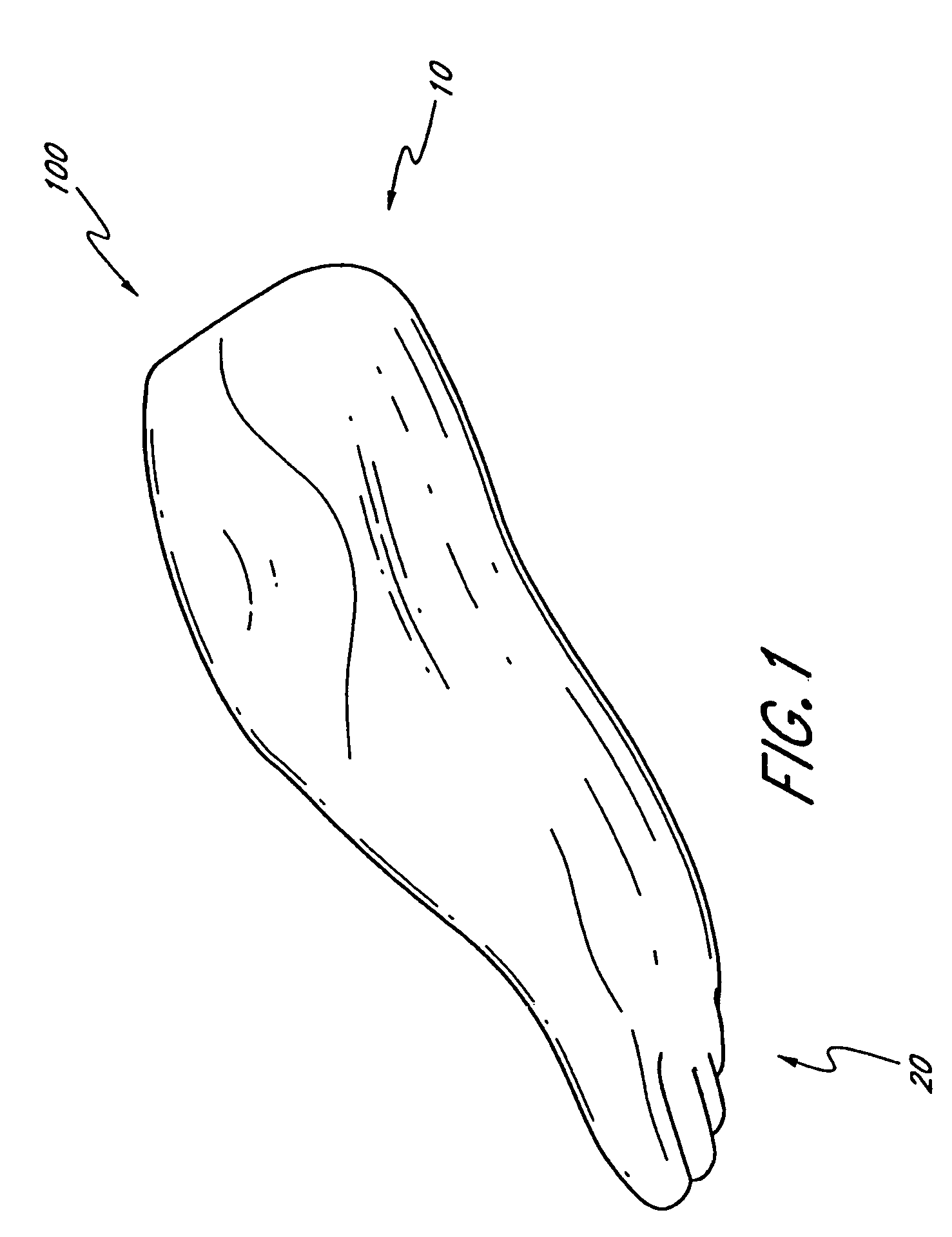
[0032]FIG. 1 illustrates one embodiment of a functional foot cover 100. Preferably, the functional foot cover 100 has the shape of a natural human foot, including a heel section 10 and a toe section 20. In one preferred embodiment, the functional foot cover 100 can be made of polyurethane or a similar material. However, the functional foot cover 100 can be made of other suitable materials, such as materials commonly used for the manufacture of prosthetic cosmeses.

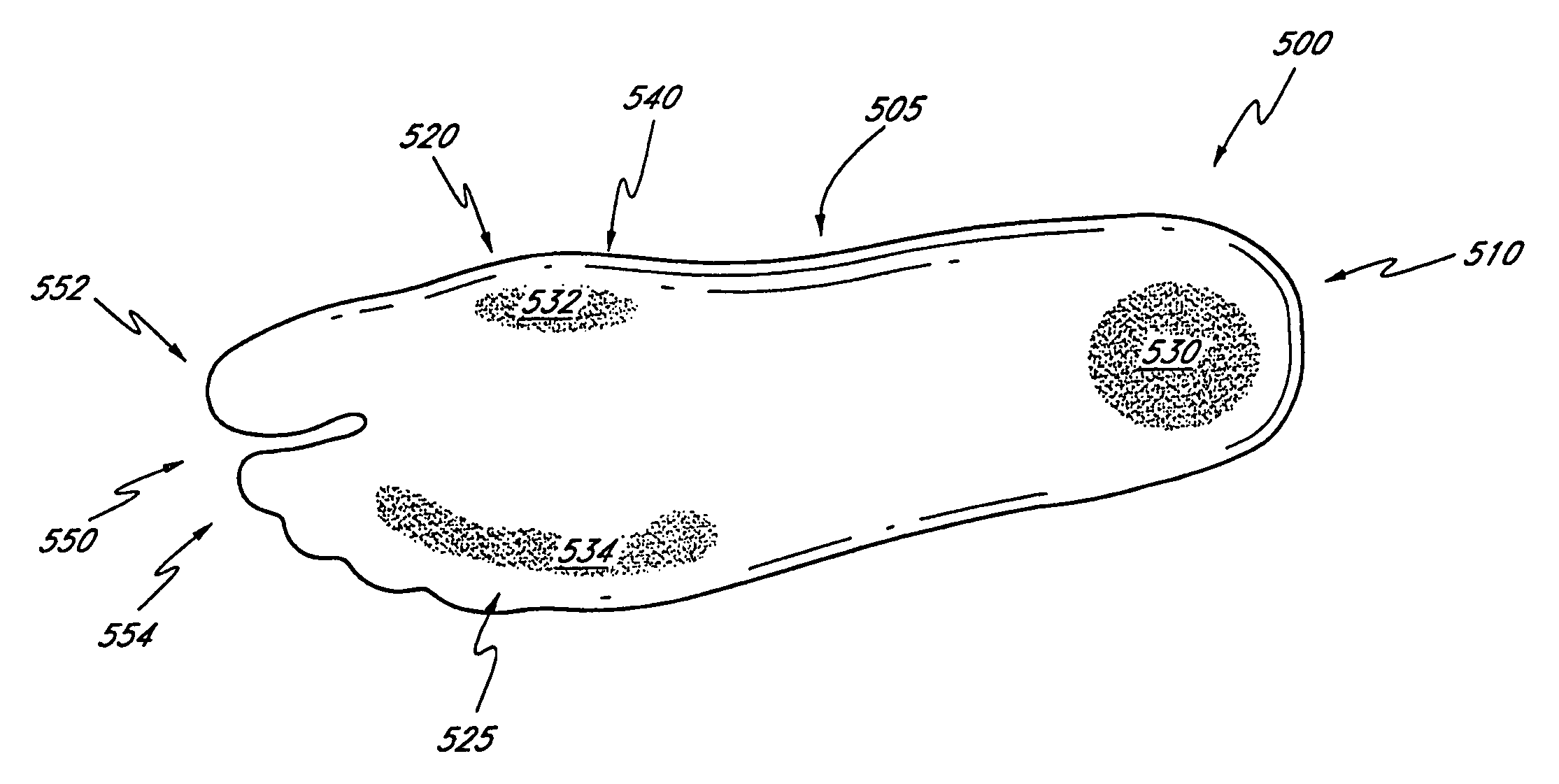
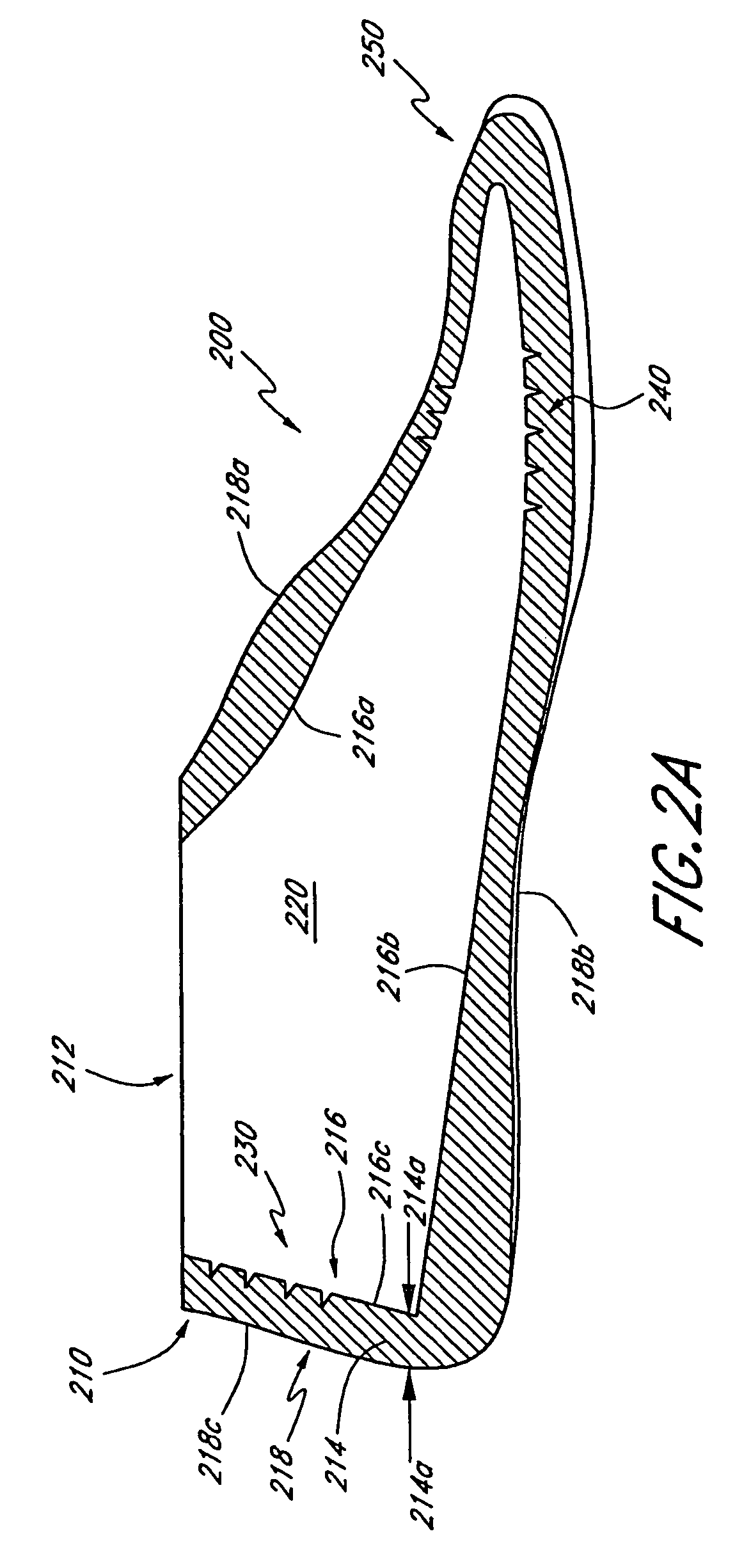
[0033]FIG. 2A illustrates a cross-section of another embodiment of a functional foot cover 200. The functional foot cover 200 is preferably configured to receive a prosthesis therein, such as the prosthetic foot 50 illustrated in FIG. 2B. In the illustrated embodiment, the prosthetic foot 50 is an Elation™ Foot...


PUM


Abstract

A cover for a foot prosthesis comprises an opening at a top end of the cover, which extends into a cavity formed within the cover, wherein the cavity is configured to receive a prosthesis therein. A wall surrounds the cavity and has the shape of a natural human foot. The wall has an inner surface and an outer surface. The wall also has a top section, a bottom section and a rear section. The bottom section defines a sole area having a toe section, a heel section, and a metatarsal region, wherein the sole area is provided with varying levels of stiffness configured to induce a desired rollover from heel-to-toe in a lateral-to-medial direction.

Description

CROSS-REFERENCE TO RELATED APPLICATIONS[0001]This application claims priority to U.S. Provisional Patent Applications No. 60 / 575,142 and No. 60 / 575,587, both filed May 28, 2004, the entire contents of which are hereby expressly incorporated by reference and should be considered a part of this specification.BACKGROUND OF THE INVENTION[0002]1. Field of the Invention[0003]The present invention relates to foot covers and, in particular, to covers for a foot prosthesis.[0004]2. Description of the Related Art[0005]Conventional prosthetic foot designs are sometimes enclosed in a cosmesis or cover to improve the aesthetic appeal of the prosthesis, as shown, for example, in U.S. Pat. No. 4,865,612 to Arbogast et al. Some conventional cosmesis designs have the shape of a human foot and are made, for example, of rubber or other flexible materials, which provide additional cushion to the prosthesis during use. However, conventional cosmeses are not designed enhance the performance of the prosth...

Claims


Application Information

Patent Timeline
Patent Type & Authority Patents(United States)
IPC IPC(8): A61F2/66A61FA61F2/00A61F2/50
CPCA61F2/66A61F2/6607A61F2002/3007A61F2002/30434A61F2002/30708A61F2002/5001A61F2002/5003A61F2002/5007A61F2002/5009A61F2002/503A61F2002/5055A61F2002/5066A61F2002/6628A61F2002/6635A61F2002/6642A61F2002/665A61F2002/6685A61F2220/0041A61F2250/0018A61F2250/0029A61F2250/0036A61F2250/0084A61F2002/30433
Inventor THORHALLSDOTTIR, HJORDISGESTSDOTTIR, ERLA SIGRIDURCLAUSEN, ARINBJORN VIGGOLECOMTE, CRISTOPHERAGNARSDOTTIR, HEIDRUN GIGJA
Owner OSSUR HF
Why Eureka
Try Eureka