Tuning-fork type piezoelectric vibrating pieces having similarly shaped vibrating-root and supporting root portions

a piezoelectric vibrating and tuning fork technology, which is applied in the direction of impedence networks, generators/motors, devices for material selection, etc., can solve the problems of significant vibration leakage, etching may be more difficult to perform with more miniaturized configurations of piezoelectric vibrating pieces, and etchant may not flow around the root portion

Inactive Publication Date: 2012-03-13
NIHON DEMPA KOGYO CO LTD
View PDF12 Cites 19 Cited by
  • Summary
  • Abstract
  • Description
  • Claims
  • Application Information

AI Technical Summary

Benefits of technology

[0011]Another embodiment of a piezoelectric vibrating device comprises a base having a first end and an opposing second end. A pair of vibrating arms extends from the first end of the base in a first direction. A vibrating root portion is situated on the base between the vibrating arms. Outboard of each vibrating arm and extending in the first direction from the first end of the base is a respective supporting arm. The width (perpendicular to the first direction) between the vibrating arms is equal to the width between each vibrating arm and its respective supporting arm. In this configuration, the vibrating root portion as well as supporting root portions situated on the base between each vibrating arm and respective supporting arm facilitate bisymmetric etching. The bisymmetry provides for a balanced configuration of the piezoelectric vibrating piece, which improves the CI value and reduces vibration leakage. In a variation of this embodiment, the respective coordinates of the vibrating root portion and supporting root portions along the first direction are the same. In another variation the supporting root portions and vibrating root portions have the same shape. The shape, or profile, can be one having angular sides or curved sides. In either case all the root portions are reliably formed by etching to have the same shape.
[0014]In some embodiments each vibrating arm can include at least one groove in which a respective excitation electrode is formed to excite the vibrating arms. Thus, the vibrating arms can be oscillated easily and CI readily lowered.

Problems solved by technology

Even small variations in the dimensions of the vibrating arms and / or root portions caused by anomalous etching produce significant vibration leakage.
Especially with increased miniaturization, etchant may not flow sufficiently around the root portions to produce desired etching rates in those locations.
Also, etching may be more difficult to perform with more miniaturized configurations of piezoelectric vibrating pieces due to anisotropy of the crystal.

Method used


Image

  • Tuning-fork type piezoelectric vibrating pieces having similarly shaped vibrating-root and supporting root portions
  • Tuning-fork type piezoelectric vibrating pieces having similarly shaped vibrating-root and supporting root portions
  • Tuning-fork type piezoelectric vibrating pieces having similarly shaped vibrating-root and supporting root portions

Examples


first embodiment

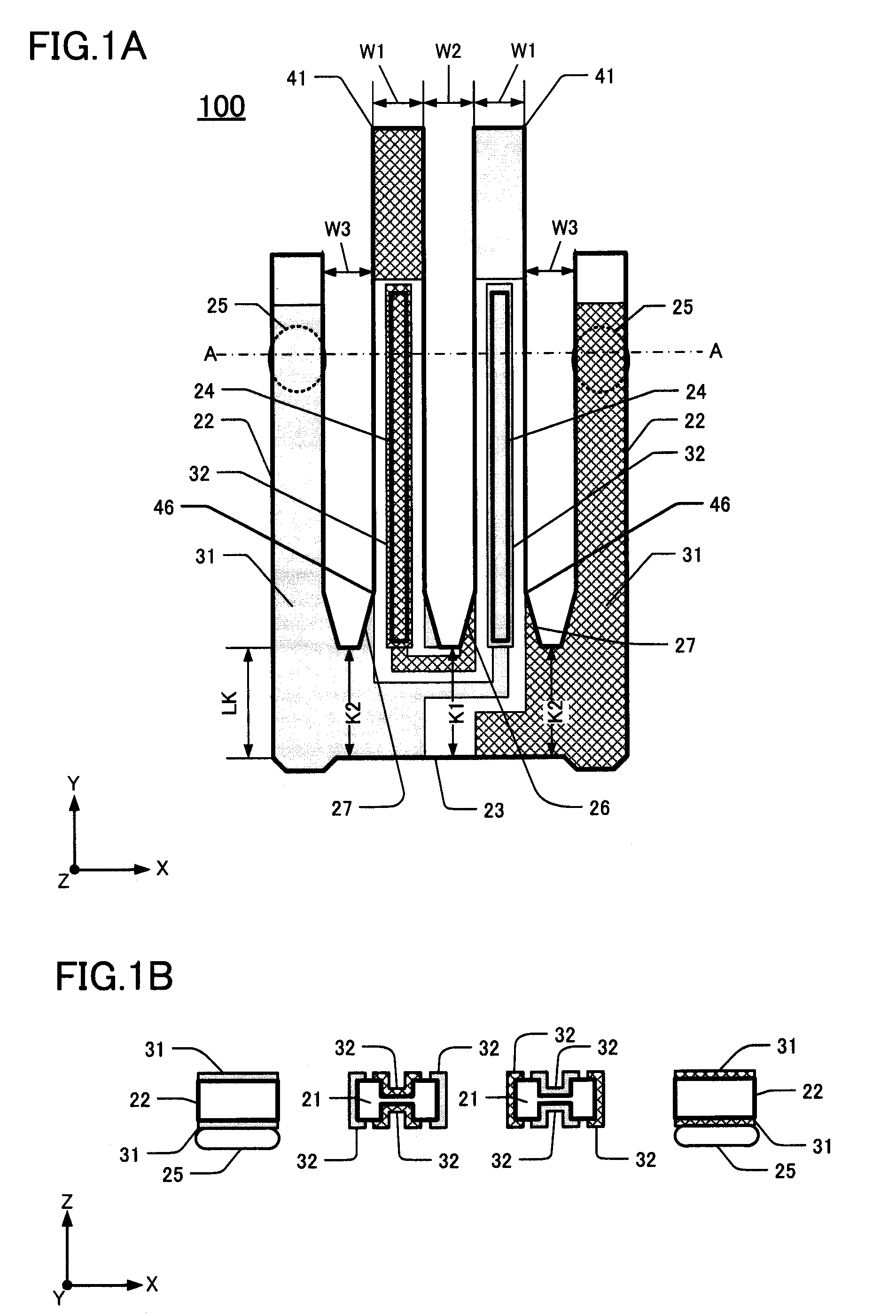
[0030]This embodiment of a tuning-fork type crystal vibrating piece 100 is shown in FIG. 1A. The crystal vibrating piece 100 comprises a pair of vibrating arms 41 and a pair of supporting arms 22. FIG. 1B is a cross-sectional view along the line A-A in FIG. 1A. The vibrating arms 41 extend from a base 23. The length LK of the base 23 (in the Y-direction) is about 0.20 mm, and the length (in the Y-direction) of each vibrating arm 41 is about 1.25 mm.

[0031]The vibrating arms 41 extend parallel to each other from the base 23. A respective groove 24 is formed on each of the upper and lower surfaces of each vibrating arm 41, yielding a total of four grooves 24 per pair of vibrating arms 41. As shown in FIG. 1B, a cross-section of a vibrating arm 41 having grooves 24 on the upper and lower surfaces has a substantially H-shaped transverse profile. The H-shaped profile is effective in reducing the CI of the crystal vibrating piece 100.

[0032]Each vibrating arm 41 has “root” portions 26, 27 a...

second embodiment

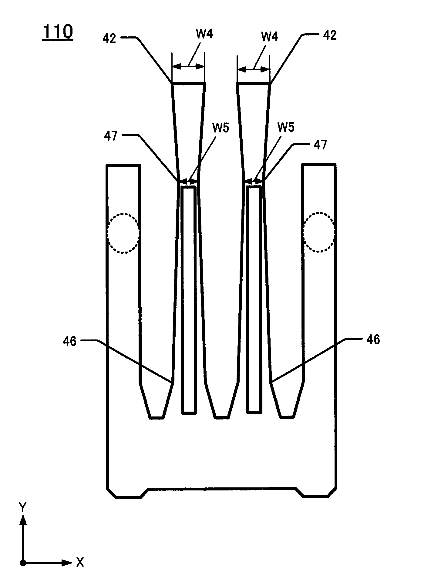
[0054]FIG. 3 shows a second embodiment of the tuning-fork type crystal vibrating piece 110, comprising a pair of vibrating arms 42. Except for the configuration of the vibrating arms 42 of this embodiment 110, other components thereof are similar to corresponding components in the first embodiment and are not described further. Also, the electrodes are not shown in FIG. 3 (or described below) to facilitate clarity.

[0055]In FIG. 3 the vibrating arms 42 extend from the base 23 and gradually become narrower with increasing distance in the Y-direction from their respective root portions. A first constriction 46 is located just distally of the root portions. The vibrating arms 42 gradually narrow with increased distance from the first constriction 46 to a second constriction 47 located near the distal ends of the vibrating arms 42. From the second constriction 47, the vibrating arms 42 gradually widen with increasing distance to the distal ends of the arms. Despite these gradations in wi...

third embodiment

[0058]This embodiment is shown in FIG. 4, and includes a tuning-fork type crystal vibrating piece 120 comprising a pair of vibrating arms 43 exhibiting increased CI stability. Except for the description of the vibrating arms 43, descriptions of other components and features of the crystal vibrating piece 120 are not provided because the other components and features are as described above in the first embodiment. Also, the electrodes are not described or shown to facilitate clarity of features actually shown.

[0059]As can be seen in FIG. 4, the vibrating arms 43 extend lengthwise from the base 23 and narrow in their root regions to a first constriction 46 situated as in the second embodiment. From the first constriction 46, the vibrating arms 43 progressively narrow to a second constriction 47. But, at the second constriction 47, the vibrating arms 43 become suddenly wider (to HW), and the width HW remains constant from the second constriction 47 to the distal tips of the arms. Thus,...


PUM


Abstract

Piezoelectric vibrating pieces are disclosed. An exemplary piece includes a base and at least a pair of vibrating arms connected to the base. The vibrating arms extend from one end of the base in a first direction. A vibrating root portion is situated between the vibrating arms. A pair of supporting arms extend, outboard of the vibrating arms, in the first direction from the one end of the base. Respective supporting root portions are situated between each vibrating arm and its outboard supporting arm, at the same position (denoted, e.g., K1, K2) in the first direction of the vibrating root portion.

Description

CROSS-REFERENCE TO RELATED APPLICATION[0001]This application claims priority to and the benefit of Japan Patent Application No. 2008-134158, filed on May 22, 2008, in the Japan Patent Office, the disclosure of which is incorporated herein by reference in its entirety.FIELD[0002]This disclosure pertains to techniques for manufacturing a tuning-fork type piezoelectric vibrating elemental device having supporting arms and particular configurations of vibrating arms. The devices are manufactured from a piezoelectric substrate comprising, for example, crystal such as quartz crystal.DESCRIPTION OF THE RELATED ART[0003]Various types of clocks, home electric appliances, and consumer electronics, and various types of commercial / industrial electrical apparatus such as information / communication devices and Office-Automation devices utilize at least one oscillator. These oscillators typically are manufactured by packaging a piezoelectric resonator, a piezoelectric vibrating device, or an IC chi...

Claims


Application Information

Patent Timeline
Patent Type & Authority Patents(United States)
IPC IPC(8): H03H9/19H01L41/09H01L41/18H01L41/22H01L41/23H01L41/29H01L41/313H03H9/215
CPCH03H9/1021H03H9/21
Inventor KAWANISHI, SHINGO
Owner NIHON DEMPA KOGYO CO LTD
Why Eureka
Try Eureka