Measuring Brillouin backscatter from an optical fibre using a tracking signal

a tracking signal and optical fibre technology, applied in the direction of reflectometers using simulated backscatter, testing fibre optic/optical waveguide devices, instruments, etc., can solve the problems of large bandwidth degrade performance, slow data acquisition time, and long process, so as to reduce the amount of data processing required and measure the time. , the effect of reducing the amount of tim

Active Publication Date: 2012-03-13
SCHLUMBERGER TECH CORP
View PDF11 Cites 9 Cited by
  • Summary
  • Abstract
  • Description
  • Claims
  • Application Information

AI Technical Summary

Benefits of technology

[0013]Performing frequency mixing of the Brillouin backscatter with a frequency that tracks a previous measurement of the Brillouin backscatter effectively confines the measurement to a known frequency window expected to contain or at least overlap the present Brillouin frequency in most circumstances. Thus, the frequency range which it is necessary to observe to locate the Brillouin frequency is very much reduced compared to the full range of possible Brillouin frequencies that is scanned according to conventional Brillouin measurement techniques. Measurement times and the amount of data processing required are thereby greatly reduced.
[0014]The method may further comprise using information relating to the Brillouin spectral line determined from processing the difference signal to update the information defining the previously measured Brillouin shift, thereby updating the frequency f1(t) of the second signal. For example, the method may comprise determining the difference δ between the actual value of the difference frequency ΔF(t) obtained by mixing the first signal and second signal and the nominal value of ΔF(t) for one or more values of t; and using the values of δ thus determined to update the information defining the previously measured Brillouin shift, thereby updating the frequency f1(t) of the second signal. In this way, any changes in the Brillouin shift caused by a change in the fibre environment from one measurement to the next can be accommodated so that the frequency tracking of the received backscatter is maintained over the long term, thus retaining the received light within the observed frequency window.

Problems solved by technology

A problem with discriminator-based techniques is the need to employ a wide input frequency spectrum to capture the full range of potential output signal frequencies.
The necessary broad bandwidth tends to degrade performance.
For these various scanning methods, the data acquisition time is typically slow, since the signals must be averaged in two dimensions.
Depending on the sampling interval in the frequency offset domain and the span of frequencies to be covered, this can be a lengthy process during which essential but sparsely used information is acquired.

Method used


Image

  • Measuring Brillouin backscatter from an optical fibre using a tracking signal
  • Measuring Brillouin backscatter from an optical fibre using a tracking signal
  • Measuring Brillouin backscatter from an optical fibre using a tracking signal

Examples


first example embodiment

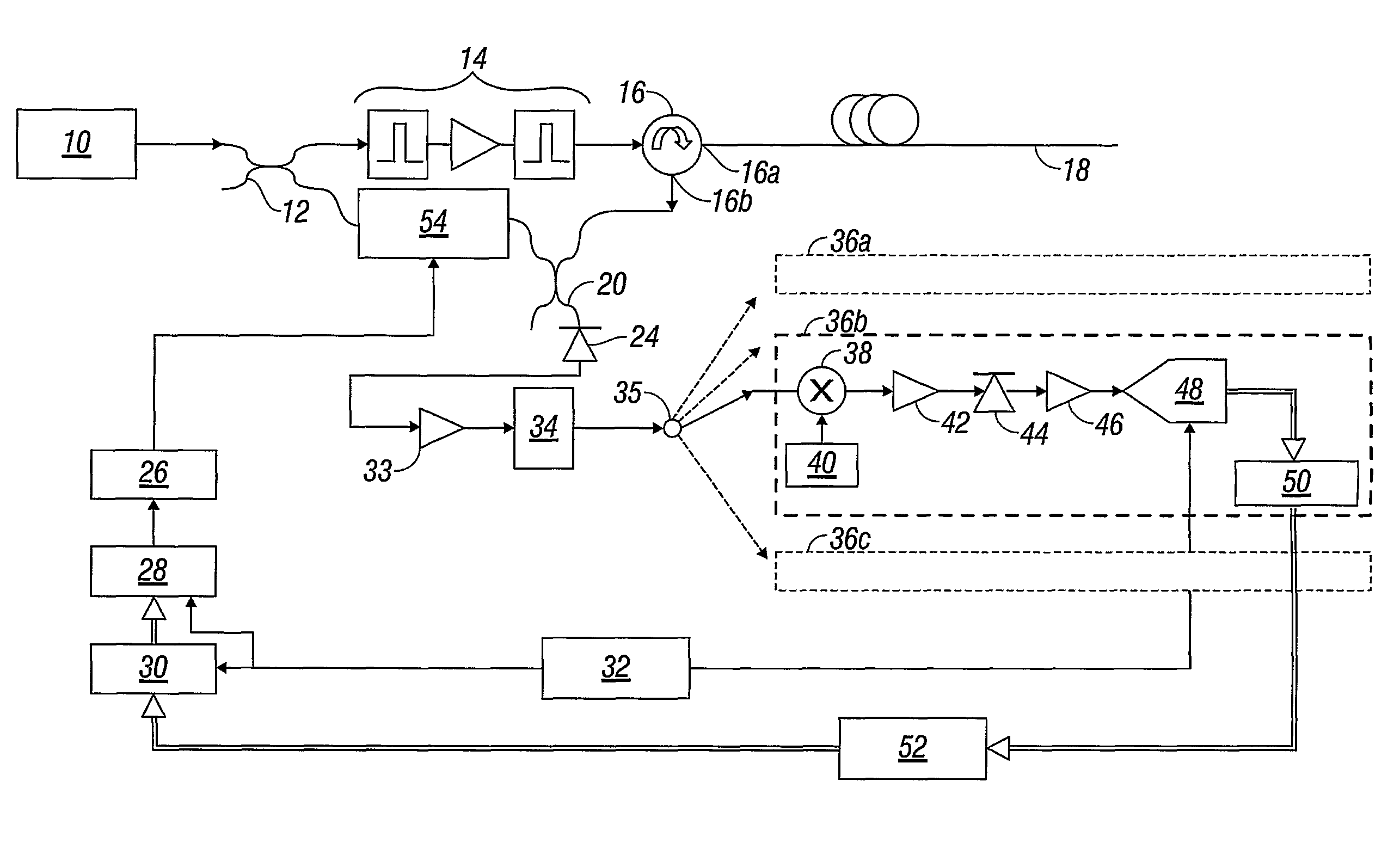
[0037]FIG. 1 shows a schematic representation of apparatus for implementing a measurement method according to an embodiment of the present invention.

[0038]An optical source 10 operable to generate narrow-band coherent light (such as a laser) produces an output beam at a frequency f0. The beam is directed into a beam splitter 12 (such as a 3 dB fibre splitter) that divides the output beam into a first part for launching into a deployed optical fibre, and a second part to be mixed with light received back from the fibre. The first part passes through a pulse forming unit 14 that produces optical probe pulses of a desired repetition frequency, pulse duration and power, suitable for probing of the deployed fibre to obtain Brillouin backscatter. In this example the pulse forming unit 14 comprises two pulse generators / gates with an amplifier between; any required combination of optical components can be used to create the necessary output, though. The pulses at f0 are then sent to an opti...

second example embodiment

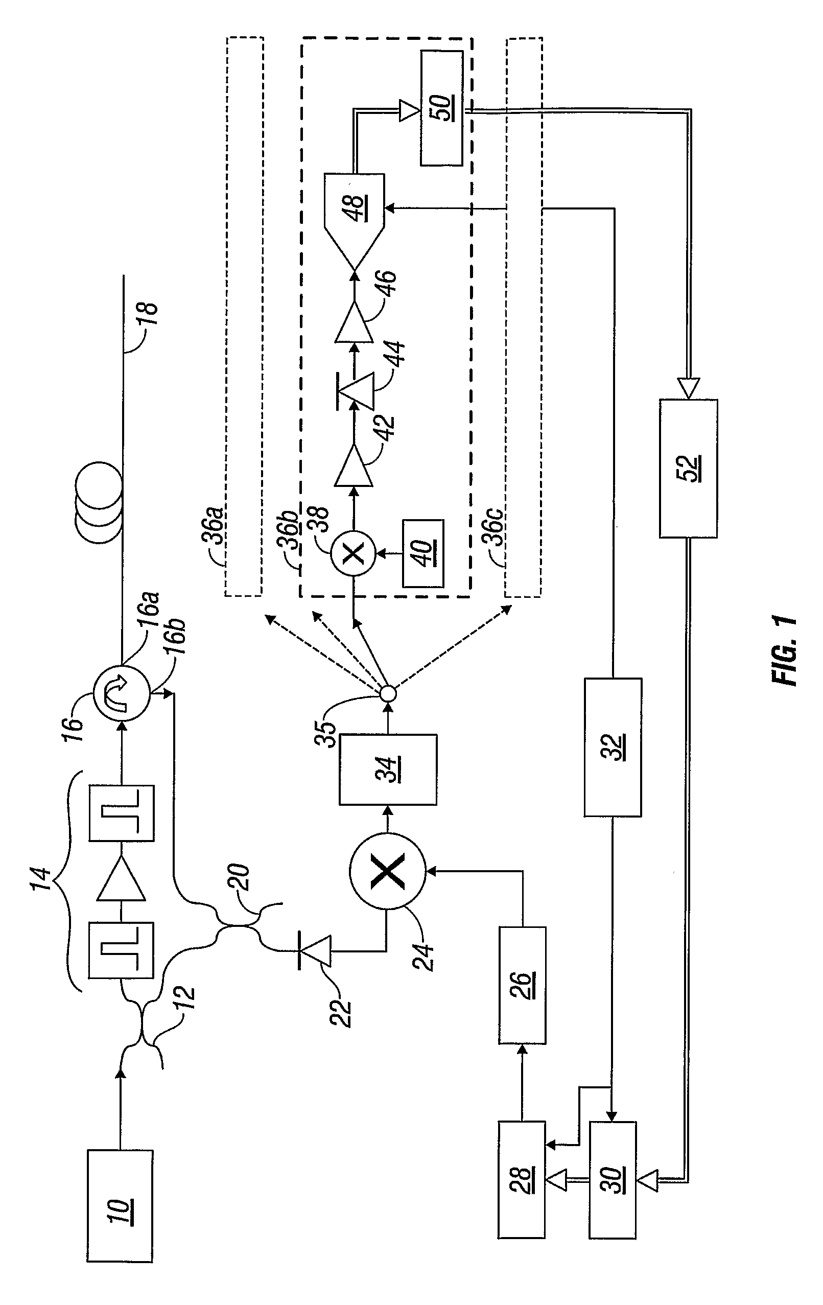
[0057]FIG. 2 shows a schematic representation of a second embodiment of apparatus according to the present invention. Like reference numerals are used for like components as compared to FIG. 1.

[0058]The second embodiment employs the same arrangement as FIG. 1 for generating and launching probe pulses in an optical fibre 18, using an optical source 10 whose output is gated and amplified to produce pulses, and launched into the fibre 18 via a circulator 16. Again, the returning Brillouin light is received at the fibre end and passed by the circulator to a beam combiner 20.

[0059]Also, the acquisition and processing components are the same as in FIG. 1. The difference frequency signal ΔF(t) is passed through a bandpass filter 34 before being divided between a plurality of parallel frequency channels 36 which produce digitised samples that are delivered from an array of memory units 50 to a processor 52.

[0060]Again as in FIG. 1, the processor 52 is further connected to a memory array 30 ...

third example embodiment

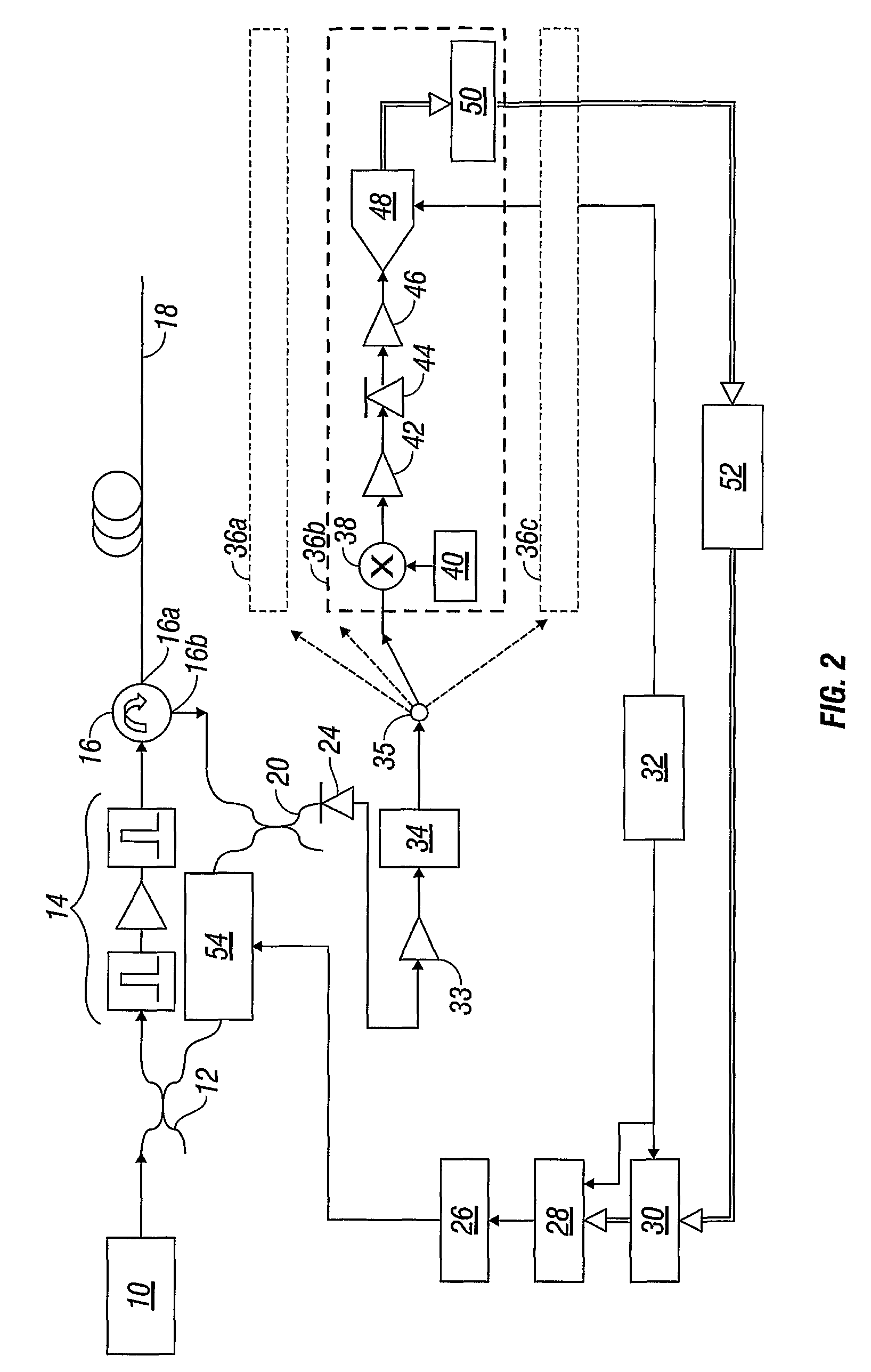
[0068]An alternative to the frequency channel acquisition approach described with regard to the first and second example embodiments is an all-digital acquisition approach which employs an analog-to-digital converter to acquire the difference signal at a rate sufficient to carry out a frequency analysis. This approach may be applied to either the electrical mixing technique of the first example embodiment or the optical mixing approach of the second example embodiment.

[0069]FIG. 3 shows a schematic representation of apparatus that uses all-digital acquisition, described only for the purposes of example in conjunction with the electrical frequency mixing approach of FIG. 1 (all-digital acquisition being equally applicable to other electrical mixing arrangements, and to optical mixing including that of FIG. 2). Hence FIG. 3 shows many features in common with FIG. 1, including the pulse generation and launch components, the intermediate difference frequency mixing in the optical detect...


PUM

PropertyMeasurementUnit
difference frequency Δfiaaaaaaaaaa
frequencyaaaaaaaaaa
wavelengthaaaaaaaaaa

Abstract

A method for measuring Brillouin backscattering from an optical fiber, includes frequency mixing a first signal with a frequency representative of the Brillouin frequency shift in backscattered light received from a deployed optical fiber with a second signal at a frequency that varies in time in the same manner as a Brillouin shift previously measured from the fiber to produce a difference signal with a difference frequency that has a nominally constant value corresponding to the situation where the received light has a Brillouin shift that matches the previously measured shift. The difference signal is acquired and processed to determine properties of the Brillouin shift and corresponding physical parameters producing the shift. The frequency mixing can be carried out optically or electrically. Techniques for acquisition of the difference signal include the use of parallel frequency measurement channels and fast rate digital sampling.

Description

BACKGROUND OF THE INVENTION[0001]1. Field of the Invention[0002]The present invention relates to a method and apparatus for measuring Brillouin backscattered light from an optical fibre used for optical time domain reflectometry.[0003]2. Description of Related Art[0004]Optical time domain reflectometry (OTDR) is a technique that uses optical fibre to make remote measurements of various parameters. A probe pulse of light is launched into an end of a fibre that is deployed through a region of interest, for example down an oil well. The pulse propagates along the fibre, and part of the light is backscattered from points along the length of the fibre and returns to the launch end, where it is detected. The propagation time to the scattering point and back is recorded as the light returns, so the location of the scattering point can be calculated using the speed of propagation in the fibre. Also, various physical parameters such as temperature, strain and pressure have an effect on how t...

Claims


Application Information

Patent Timeline
Patent Type & Authority Patents(United States)
IPC IPC(8): G01N21/00
CPCG01D5/35364G01M11/319G01D5/353E21B47/007E21B47/07
Inventor HARTOG, ARTHUR H.
Owner SCHLUMBERGER TECH CORP
Why Eureka
Try Eureka