System and method for performing optical navigation using scattered light

a technology of optical navigation and scattered light, applied in the direction of solid-state devices, instruments, material analysis, etc., can solve the problems of difficult to accurately determine the displacement of the optical computer mouse relative to the navigation surface, and achieve the effect of reducing the volume of the system, large field of view, and high contrast fram

Active Publication Date: 2012-03-20
PIXART IMAGING INC
View PDF16 Cites 77 Cited by
  • Summary
  • Abstract
  • Description
  • Claims
  • Application Information

AI Technical Summary

Benefits of technology

[0004]A system and method for performing optical navigation uses light scattered from the navigation surface to produce frames of image data to estimate displacement with respect to a target surface. The scattered light is produced from an illumination beam of light emitted along a first optical axis onto the target surface. The illumination beam of light also produces a specular reflected beam of light along a second optical axis. The scattered light about a third optical axis, which is offset by a predefined angle with respect to the second optical axis, is received at an image sensor array to produce the frames of image. The configuration of the system allows the volume of the system to be minimized while maintaining a large field of view and producing high contrast frames of image data over a wide variety of navigation surfaces, even surfaces of glass tables, i.e., surfaces of sheets of glass on tabletops with or without support directly below the field of view.

Problems solved by technology

Image contrast is important for an optical navigation system since the noise in the system will otherwise dominate, which makes it difficult to accurately determine the displacement of the optical computer mouse relative to the navigation surface.
While some navigation surfaces readily produce high contrast frames of image data, other navigation surfaces such as surfaces of glass tables, i.e., surfaces of sheets of glass on tabletops or glass tables with no structure directly under the field of view, do not when probed by conventional optical mice.

Method used


Image

  • System and method for performing optical navigation using scattered light
  • System and method for performing optical navigation using scattered light
  • System and method for performing optical navigation using scattered light

Examples


Embodiment Construction

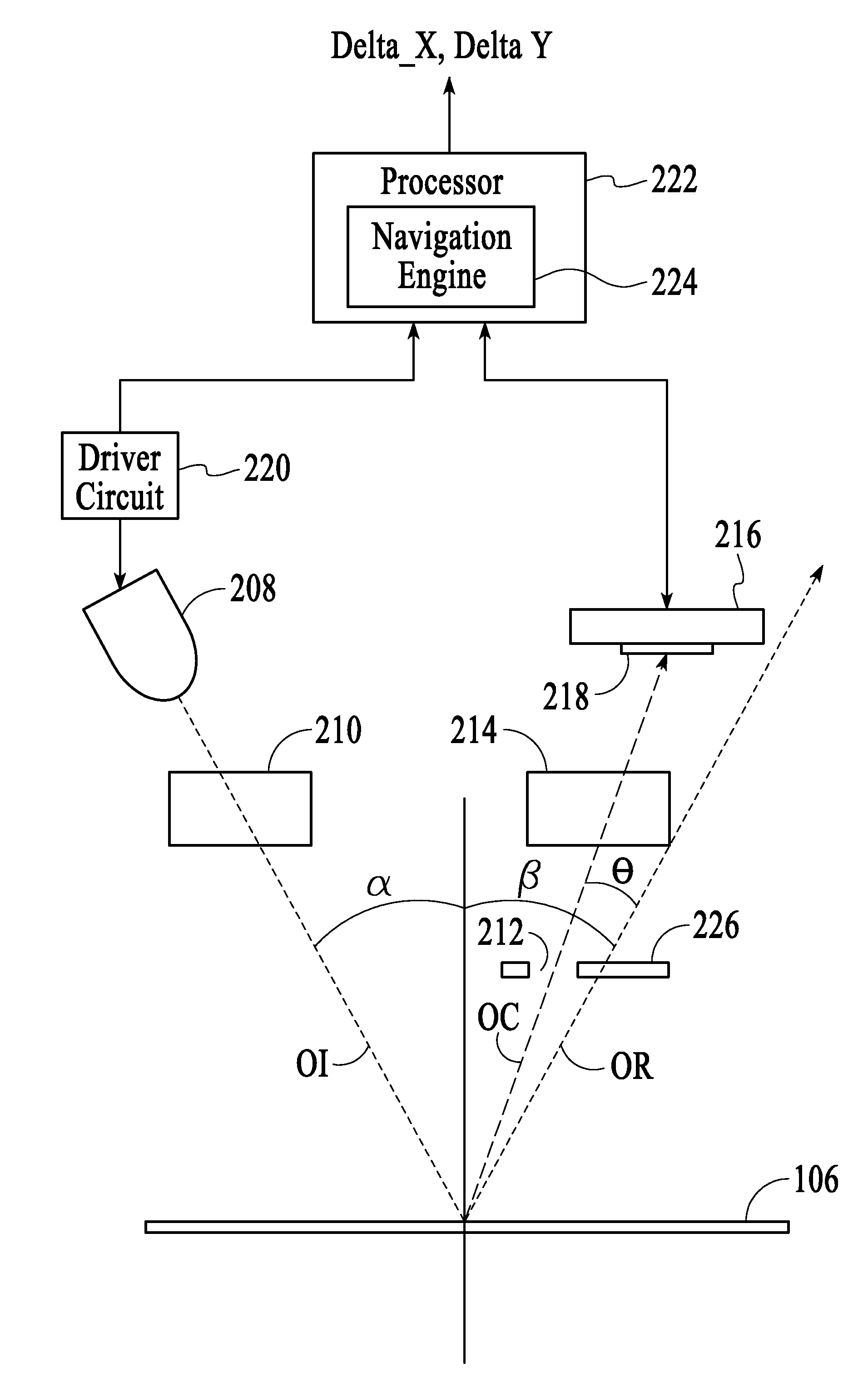
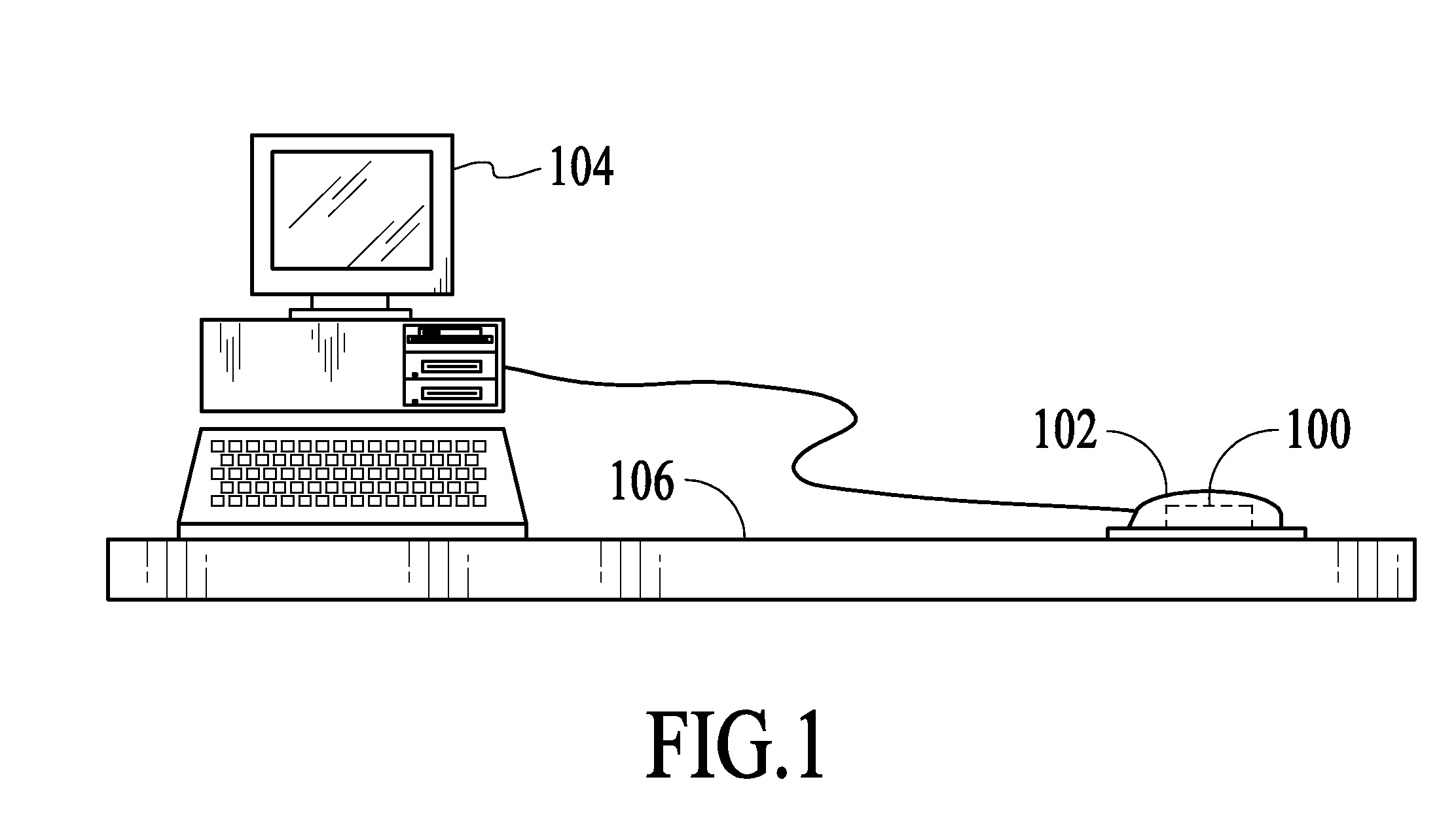
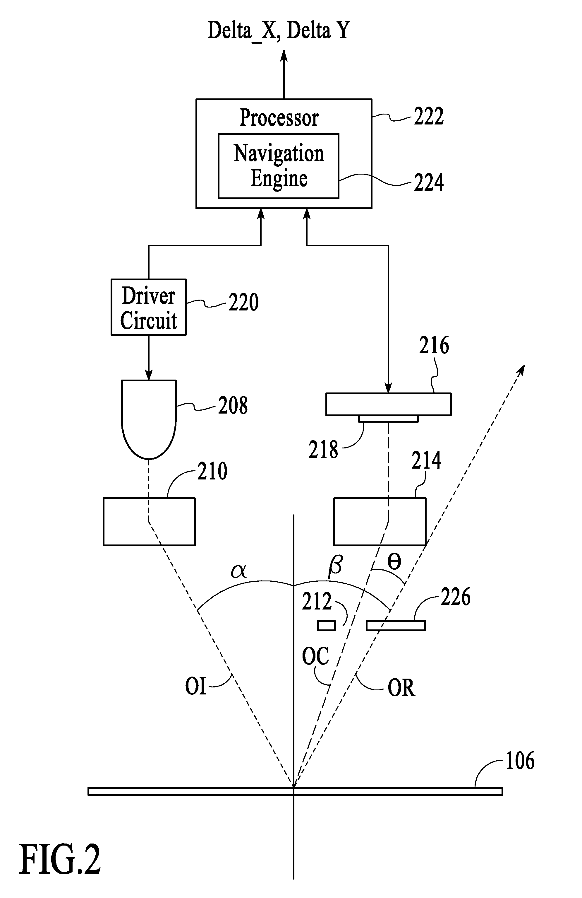
[0016]With reference to FIG. 1, an optical navigation system 100 in accordance with an embodiment of the invention is described. As shown in FIG. 1, the optical navigation system 100 is included in an optical computer mouse 102, which is connected to a computer 104. In other embodiments, the optical computer mouse 102 may be wirelessly connected to the computer 104. In this implementation, the optical navigation system 100 is used to optically track the movements of the optical mouse 102 as the optical mouse is manipulated over a navigation or target surface 106 by a user to control a cursor displayed on the computer 104. However, in other implementations, the optical navigation system 100 can be used in different products for various tracking applications. As described in detail below, the optical navigation system 100 is designed such that that the volume of the system is minimized while maintaining a large field of view and producing high contrast frames of image data over a wide...


PUM

PropertyMeasurementUnit
angle of incidenceaaaaaaaaaa

Abstract

A system and method for performing optical navigation uses scattered light to produce frames of image data to estimate displacement with respect to a target surface. The scattered light is produced from an illumination beam of light emitted along a first optical axis onto the target surface. The illumination beam of light also produces a specularly reflected beam of light along a second optical axis. The scattered light about a third optical axis, which is offset by a predefined angle with respect to the second optical axis, is received at an image sensor array to produce the frames of image.

Description

BACKGROUND OF THE INVENTION[0001]Optical navigation systems detect relative movements between the optical navigation systems and target or navigation surfaces to perform tracking operations. An optical navigation system uses a light source, such as a light-emitting diode or a laser diode, to provide illumination light on a navigation surface and an image sensor to successively capture frames of image data in response to the illumination light reflected off the navigation surface. The optical navigation system compares the successive frames of image data and estimates the relative movements between the optical navigation system and the navigation surface based on the comparison between the current frame of image data and a previous frame of image data. The optical navigation system is able to track the relative movements between the optical navigation system and the navigation surface by continuously capturing and comparing frames of image data.[0002]Optical navigation systems are co...

Claims


Application Information

Patent Timeline
Patent Type & Authority Patents(United States)
IPC IPC(8): G01N21/86H01L27/00G06F3/0354
CPCG06F3/0317
Inventor GROT, ANNETTE C.
Owner PIXART IMAGING INC
Why Eureka
Try Eureka