Eureka AIR delivers breakthrough ideas for toughest innovation challenges, trusted by R&D personnel around the world.

Coupling arrangement and system for continuous haulage conveyor

a conveyor and coupling arrangement technology, applied in the direction of conveyors, mechanical conveyors, packaging, etc., can solve the problems of increasing the unit increasing the cost of rom material purchase, and having an enormous detrimental effect on the viability of mining operations, so as to reduce the loss of production associated know-how, reduce downtime, and be convenient to extend or shorten the

Inactive Publication Date: 2012-03-27
PIETABCH MICHAEL
View PDF35 Cites 7 Cited by
  • Summary
  • Abstract
  • Description
  • Claims
  • Application Information

AI Technical Summary

Benefits of technology

[0027]The connector advantageously permits reliable and efficient connection / separation of conveyor sections. The connector and system is also advantageously adaptable to permit discrete sections of conveyor belt to be removed and replaced for maintenance or repair, or one or more belt sections to be removed or inserted to shorten or lengthen the belt as required.
[0043]It will be appreciated that one or more forms of the present invention provide a major benefit to operators and users in providing a dynamic haulage system, whereby the belt of the system can be readily extended or shortened, or damaged sections replaced, with reduced downtime and loss of production associated know systems. Being able to uncouple a section or sections of belt for replacement or shortening of the system, or couple in new or additional section or sections of belt to repair or extend the belt provides a far superior system than known systems. In providing adaptability of the haulage system through a dynamic system, reduced downtime, reduced loss of revenue and lost production, reduced labour charges, as well as improved operating characteristics, provides significant advantages.

Problems solved by technology

The purchase of a fleet of appropriate trucks involves a considerable capital cost, as does the establishment and maintenance of roads of sufficient bearing capacity to bear the load of heavily laden trucks.
It follows, therefore, that there will be an ever increasing unit cost of ROM material over time, as the mine progresses.
This variable cost, combined with the substantial amortized capital cost, have an enormous detrimental effect on the viability of mining operations.
Therefore, it is normal, for such systems, to spend a considerable amount of time selecting the path to ensure an uninterrupted straight path is achievable.
A further problem lies with the mine environment.
As would be expected, there is a considerable volume of dust, mud and water, which infiltrate and generally envelope all equipment within the mine zone.
Whilst this can be accommodated for in a horizontal orientation, when the belt is inclined, the traction force is reduced below a useful level, and drive can be substantially lost.
A further problem is the size limitation of the system.
The belt of the conveyor system is susceptible to severe damage from large, angular rocks, partly because of the punching shear force established between the sharpness of the rocks on the belt and the support from underneath, as a result of the impact of the rocks.
Typically such systems are limited to rock sizes of less than 300 mm, and thus any material to be removed from the pit must be crushed to a suitable size.
A significant problem associated with this arrangement is the cost of crushing.
Unfortunately, it has been shown in practice that, typically, ROM material comprises a very high percentage of material above 300 mm, up to a common maximum of 1000 mm, not withstanding extremely large “renegade” rocks of unpredictable size.
Thus, this initial crushing is necessary, but based on the limitations of the conveying system rather than on a sound economic basis.
With every transfer of material between transport mediums representing additional cost per tonne processed, further detracting from the economic viability of such a system.
Using the truck based system, this waste material is taken directly to a dumping site, as crushing of such material is of no practical benefit, and represents an enormous and pointless waste of resources.
It has been found that such an arrangement cannot be used on a significant slope without slippage of material thereon.
If the endless belt becomes worn or damaged, the brackets could in theory be removed and reapplied to a replacement endless belt, though the ensuing down time and loss of production would make this process inefficient and high cost.
Removing a worn or damaged section of an endless belt also requires lengthy downtime with corresponding loss and disturbance to production, with corresponding increase in costs and time.
Joining the replacement section to the original belt and edges can introduce inherent weaknesses into the belt system, not least because the edges are used to support the belt and load.
Replacement bonded or spliced joints can introduce weaknesses, with potential failure of the joint under tensile load or problems in traversing pulleys.
Another problem with known continuous haulage systems is a that each system is initially designed and constructed for a particular application or site, and they generally lack adaptability to be readily extended or change direction as the site e.g. long wall mine site, extends its workings, or for disassembly of the system for removal, such as to another site.
Such connectors have to endure large tensile and shear forces because they bear part of the downward weight of the load, as well as tensile longitudinal forces in the direction of conveying, thereby often resulting in premature wear and failure.
There is a lengthy and complex procedure in rejoining the new section to the previous ends, resulting in lengthy downtime and loss of productivity.
When such connections or belts fail, it is often necessary to replace the mechanical piano type connector completely or splice in a new portion of belt.
furthermore, it is difficult to form a strong secure connection between an end of the original edge portion and an end of the new edge portion such that the joint can reliably take longitudinal forces in conveying the belt and load.
This arrangement leads to a stiffer join which can cause problems when the belt requires flexibility to traverse horizontal or vertical return wheels, corners or pulleys.
Inflexibility or long joins potentially leads to failure or more repairs.
Also, where a repair is possible, downtime in replacing the damaged or worn section and joining edge portions is both lengthy and costly.

Method used


Image

  • Coupling arrangement and system for continuous haulage conveyor
  • Coupling arrangement and system for continuous haulage conveyor
  • Coupling arrangement and system for continuous haulage conveyor

Examples


Embodiment Construction

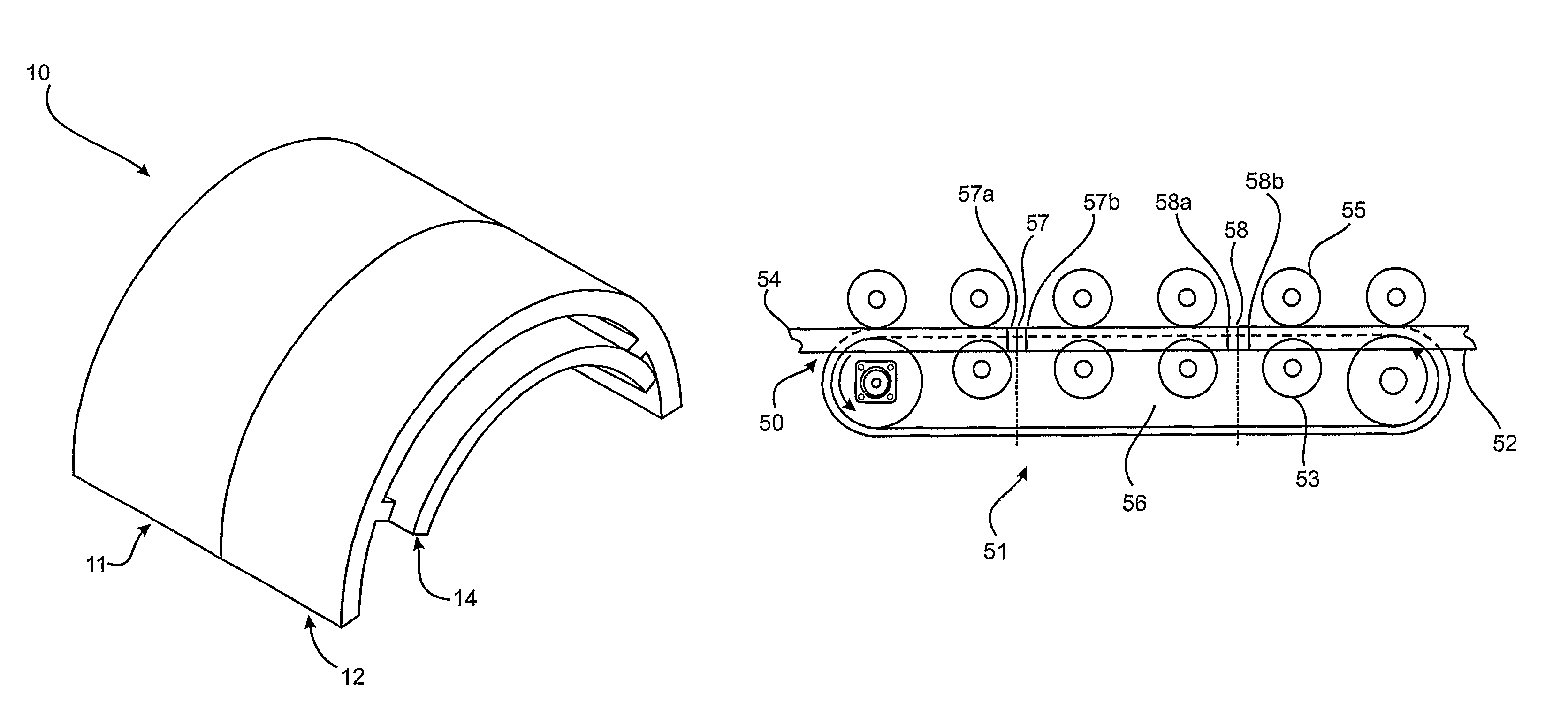
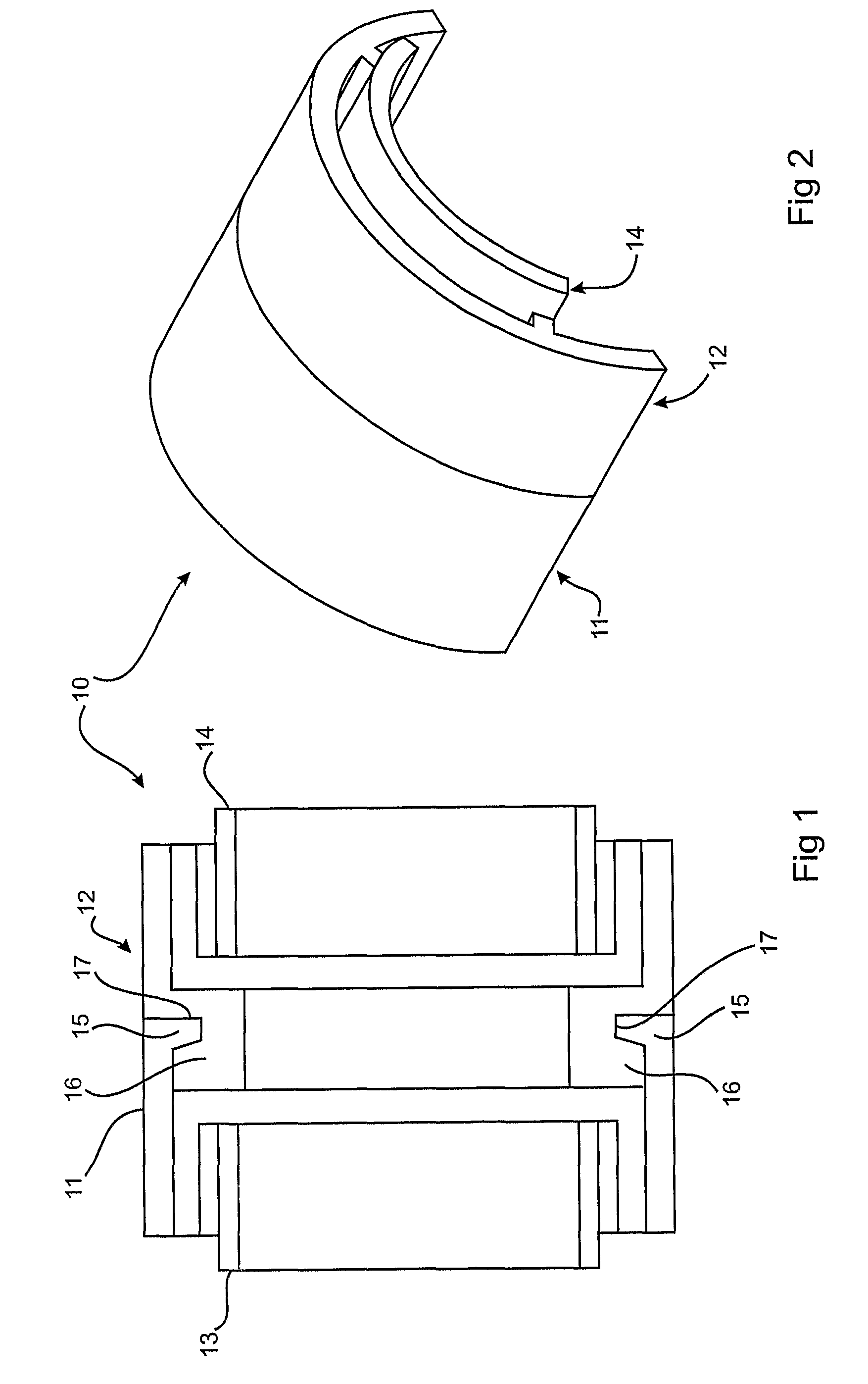
[0056]FIG. 1 shows male 11 and female 12 coupling portions of an embodiment of the coupling device 10 according to a preferred embodiment of the present invention.

[0057]FIG. 2 shows a corresponding perspective top view of the same coupling device 10. As illustrated in FIG. 1, the male coupling portion 11 includes the raised portion 15 extending around an inner circumference of an end of the male coupling portion. This projecting portion 15 is arranged to engage with a corresponding channel 17 of the same profile provided in the female coupling portion 12. As can be seen, the profile of the protruding portion 15 and corresponding channel 17 are configured to be the same size to provide engagement which positively holds the two portions together whilst minimizing movement. This is further enhanced by a return portion 16 being provided on the female portion 12. In the embodiment shown, both the male and female portions include a bridge 13, 14, each arranged to receive a respective tens...


PUM


Abstract

A connector, and coupling system, for portions of a belt for a conveyor system. A connector (10),(60) has inter-cooperating releasable coupling portions (11),(12),(61),(62). These can be provided at respective ends of edge portions of a conveyor belt to be coupled. The releasable coupling portion (male / female) of one belt portion is arranged to releasably couple to the corresponding respective coupling portion (female / male) for the end of a second belt portion. The connector system permits discrete sections of conveyor belt to be removed and replaced for maintenance or repair, or one or more belt sections to be removed or inserted to shorten or lengthen the belt as required.

Description

TECHNICAL FIELD[0001]The present invention relates to continuous haulage systems, such as suspended continuous haulage systems for conveying bulk materials like iron ore and coal.BACKGROUND[0002]Run of Mine (ROM) material is defined as any free material from a mine, including both ore and waste material. In the economic analysis of the viability of a mine, a vital consideration lies in the assessment of the cost of transporting (ROM) material following extraction.[0003]Typically, the material is removed by purpose built trucks, capable of transporting many tens of tonnes of material at a time. The ROM material is loaded onto the trucks, either from temporary stockpiles or directly from extraction. The trucks then travel from the pit to the waste material dump or to the ore crushing plant, depending on the quality of material for the particular load.[0004]The purchase of a fleet of appropriate trucks involves a considerable capital cost, as does the establishment and maintenance of r...

Claims


Application Information

Patent Timeline
Patent Type & Authority Patents(United States)
IPC IPC(8): B65G17/00
CPCB65G15/08B65G2201/045B65G2207/30
Inventor PIETSCH, MICHAEL
Owner PIETABCH MICHAEL
Why Eureka
Eureka Blog
Learn More