
Video game controller charging system having a docking structure

a charging system and video game controller technology, applied in the direction of coupling device connection, sport apparatus, transportation and packaging, etc., can solve the problems of frequent replacement or recharging of batteries, accessory devices cannot be connected to the charging station, and the battery cannot be replaced or recharged frequently

Active Publication Date: 2012-03-27
NYKO TECH
View PDF33 Cites 9 Cited by
  • Summary
  • Abstract
  • Description
  • Claims
  • Application Information

AI Technical Summary

Benefits of technology

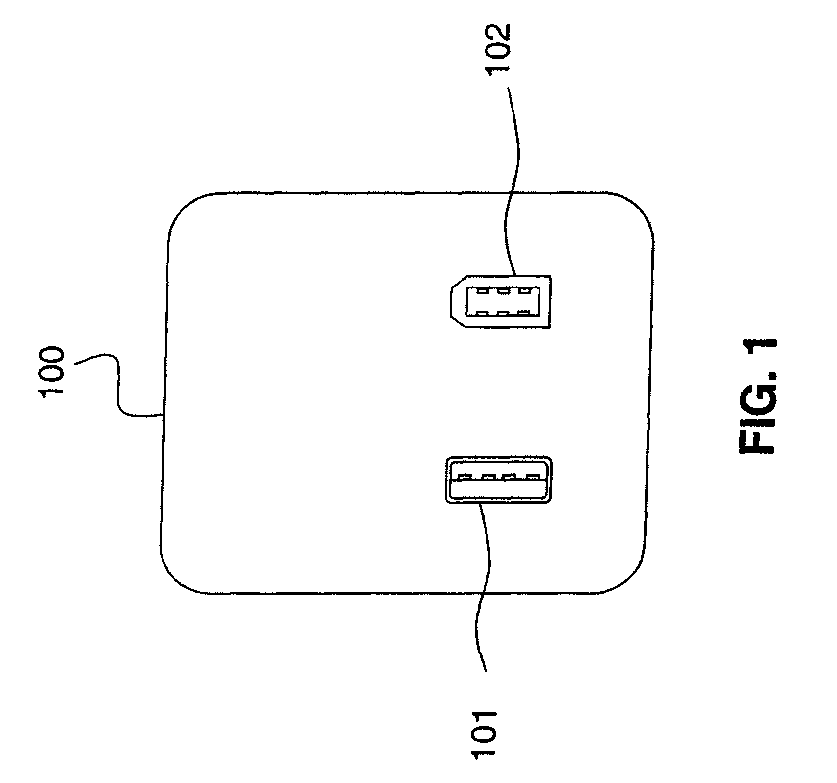
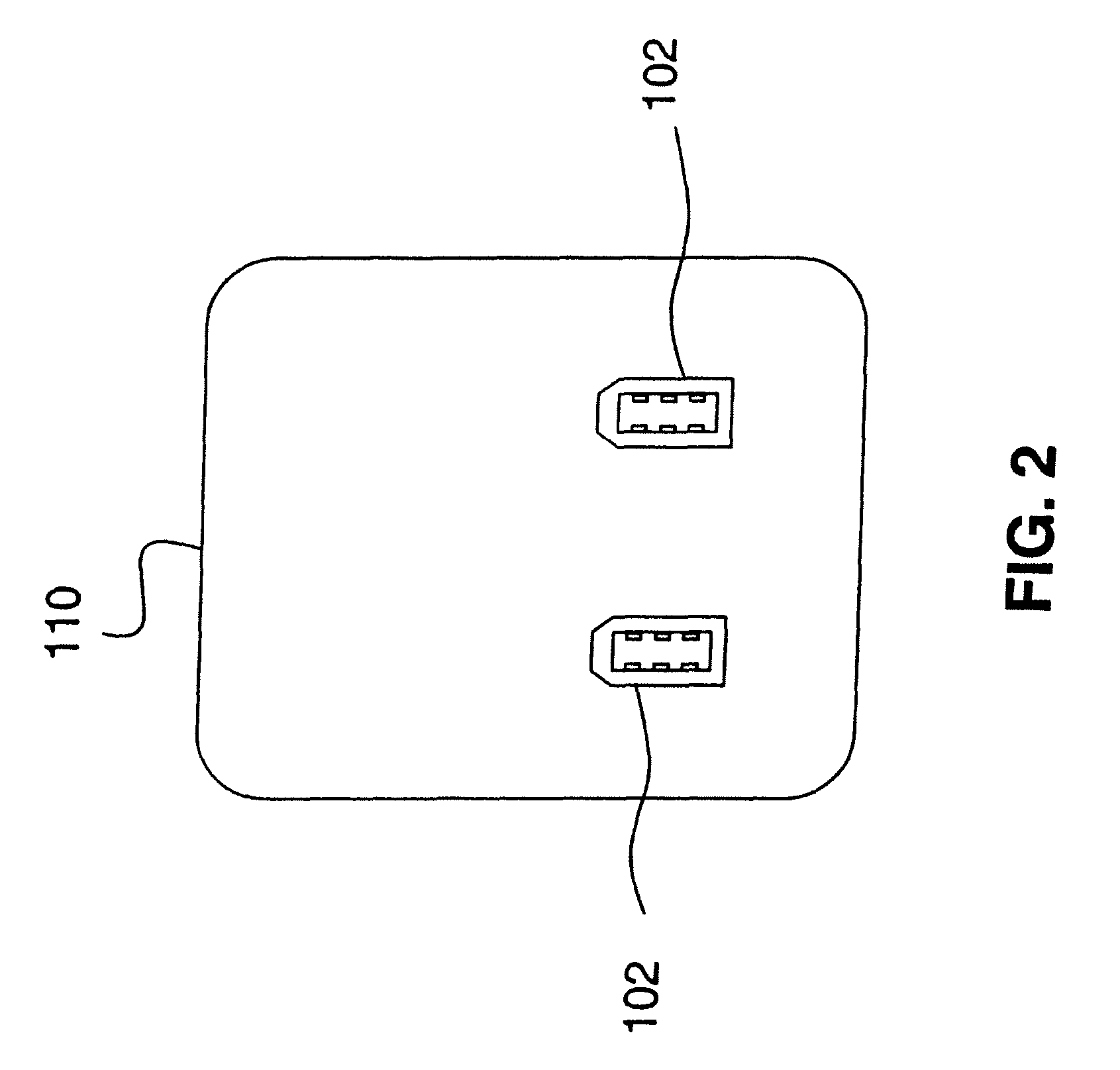
"The patent text describes a video game controller charging system that uses a base and a male mini-USB connector to charge video game controllers. The system also includes a current detector and an indicator to show the charging status. The system can also have an AC-to-DC converter to convert external power to DC power for the video game controllers. The charging system can also be used with an external adapter and a recess on the base to connect to the video game controllers. The power adapter can be used to recharge electronic devices and has a USB port and a FireWire port for recharging. The system provides a convenient and efficient way to charge video game controllers and accessories."

Problems solved by technology

Frequent use of these battery-powered accessory devices drains the batteries and requires frequent replacement or recharging of the batteries.
Frequent replacement of batteries can be expensive, and as a result, many accessory devices utilize rechargeable batteries.
If the plug on the charging station or the accessory device is broken or damaged, the accessory device can no longer be connected to the charging station.
These plugs can be small and / or fragile, as the accessory device itself is often a small, compact device.
These small plugs can be easily bent or broken, rendering the charging station inoperable.

Method used


Image

  • Video game controller charging system having a docking structure
  • Video game controller charging system having a docking structure
  • Video game controller charging system having a docking structure

Examples


Embodiment Construction

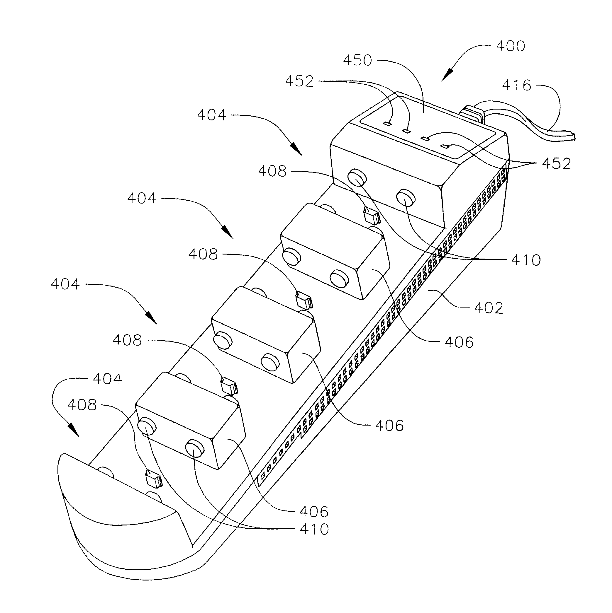
[0063]In one embodiment, a video game controller charging system is provided. The video game controller charging system includes a base, at least one structure on the base for providing physical support to at least one video game controller while it is being charged, and at least one DC port on the base configured to couple to and provide DC power to a power input port of the at least one video game controller. In some embodiments, the video game controller charging system may include a current detector, a charging status indicator, at least one docking bay, and / or an AC-to-DC converter adapted to convert externally supplied power to the DC power provided to the power input port of at least one video game controller. In other embodiments, the base of a charging system (or “charging station”) may include a recess having at least one electrical contact and a power input for connection to a power supply, the power input being electrically coupled to the at least one electrical contact....


PUM


Abstract

A video game controller charging system is provided. The video game controller charging system includes a base; at least one structure on the base for providing physical support to at least one video game controller while it is being charged; and at least one DC port on the base configured to couple to and provide DC power to a power input port of the at least one video game controller. The video game controller charging system may also include a current detector, a charging status indicator, at least one docking bay, and / or an AC-to-DC converter adapted to convert externally supplied power to the DC power provided to the power input port of at least one video game controller. The base of a charging station may include a recess having at least one electrical contact and a power input for connection to a power supply.

Description

CROSS-REFERENCE TO RELATED APPLICATION(S)[0001]This application is a continuation-in-part of pending application Ser. No. 11 / 581,137, filed on Oct. 13, 2006 now abandoned, the entire content of which is expressly incorporated herein by reference.[0002]This application also claims priority to and the benefit of U.S. Provisional Application No. 60 / 982,364, filed Oct. 24, 2007, the entire content of which is also incorporated herein by reference.FIELD OF THE INVENTION[0003]The present invention relates to charging systems for consumer electronics devices, and more particularly to charging systems for hand-held video game controllers.BACKGROUND[0004]Hand-held and portable electronic devices have become increasingly widespread and are used daily by many consumers. Examples of such devices include cellular phones, pagers, CD and MP3 players, digital organizers, video game units, digital cameras, and many other electronic devices. Most of these hand-held and portable devices rely on batter...

Claims


Application Information

Patent Timeline
Patent Type & Authority Patents(United States)
IPC IPC(8): H02J7/00
CPCH01R31/06A63F13/02H02J7/0044H02J7/0027H02J7/0013H02J2310/22A63F13/90A63F13/98H02J7/0045
Inventor NAVID, AMIR
Owner NYKO TECH
Learn More