Focusing apparatus and method

a technology of focusing apparatus and focusing method, which is applied in the direction of microscopes, telescopes, instruments, etc., can solve the problems of slow response time, limited mechanical adjustment, and inability to use commercial methods, and achieve the effect of reducing the spherical aberration introduced by the high na objective lens

Active Publication Date: 2012-03-27
OXFORD UNIV INNOVATION LTD
View PDF13 Cites 10 Cited by
  • Summary
  • Abstract
  • Description
  • Claims
  • Application Information

AI Technical Summary

Benefits of technology

[0012]According to one aspect of the present invention there is provided a focusing apparatus for use with an optical system having a high NA objective lens, the apparatus including an image forming and capturing means for forming an image in an intermediate image zone, and for capturing an image by receiving and refocusing light from a selected focal plane within said intermediate image zone, and a focus adjusting means for adjusting the position of the selected focal plane within the intermediate image zone, wherein said image forming and capturing means includes at least one high NA lens whereby, in use, spherical aberration introduced by the high NA objective lens is reduced.
[0013]The invention makes it possible to refocus the optical system rapidly at different distances from the objective lens without introducing spherical aberration. Therefore, in the case of a microscopic imaging system, an image can be obtained from different planes within the specimen, so allowing axial scanning without moving either the specimen or the objective lens. In the case of an illuminating system, an image (that is, a light pattern) can be focused onto an object at different distances from the objective, again without introducing spherical aberration.
[0014]In one preferred embodiment, the image forming and capturing means includes a first high NA lens for forming an image in the intermediate image zone and a second high NA lens for receiving and refocusing light from the intermediate image zone, and the focus adjusting means includes means for adjusting the axial position of the second high NA lens relative to the first high NA lens. In this embodiment the components of the system can be set out in a co-axial arrangement, which provides for compact packaging. There is also no significant loss of light as it passes through the apparatus, apart from normal transmission losses.
[0016]In another preferred embodiment, the image forming and capturing means includes a high NA lens and a reflective element for reflecting the image formed by the high NA lens back into the same high NA lens so as to capture an image from a selected focal plane within said intermediate image zone, and wherein the focus adjusting means includes means for adjusting the axial position of the reflective element. This form of the system allows for very rapid refocusing, since only the reflective element has to be moved. As the reflective element may be a very small and light mirror, rapid adjustment is possible, for example using a piezo transducer.
[0018]Advantageously, the polarizing beam splitter is constructed and arranged to transmit incident light having a first polarization in the direction of a first axis and to reflect light having a second polarization in the direction of a second axis, the apparatus including a first image forming and capturing means including a first high NA lens and a first reflective element for forming and capturing an image in a first intermediate image zone on said first axis, and a second image forming and capturing means including a second high NA lens and a second reflective element for forming and capturing an image in a second intermediate image zone on said second axis, and means for recombining said first and second captured images. This arrangement provides the advantage that all the light passing through the beam splitter is captured, resulting in a brighter image.
[0027]According to another aspect of the invention there is provided a method of focusing an optical system having a high NA objective lens, the method including forming an image in an intermediate image zone using at least one high NA lens, capturing an image by receiving and refocusing light from a selected focal plane within said intermediate image zone, and adjusting the position of the selected focal plane within the intermediate image zone, whereby spherical aberration introduced by the high NA objective lens is reduced.

Problems solved by technology

However, there are two major drawbacks to this approach:
(i) The speed at which mechanical adjustments can be carried out is limited by the mass of the object being moved (the objective or the specimen), which typically leads to slow response times.
However, this method is not employed commercially as it has the following drawbacks:
(ii) The discrepancy between the large numerical aperture (NA) of the objective lens and the small NA of the imaging optics that focus the image on the detector introduces a large amount of spherical aberration when the detector is not located at its optimum designed position relative to the objective.
As a result, the image quality at the shifted focal plane is seriously reduced, the loss of quality becoming progressively worse as the detector displacement increases.
This causes real problems in most applications and especially in non-linear microscopy.
(iii) In any sectioning technique such as confocal microscopy, Nipkow disc microscopy or structured illumination microscopy, the presence of spherical aberration leads to an apparent loss of image sectioning.
This is very detrimental to such imaging modes as they all rely heavily on consistent sectioning to be of practical value.
However, mechanical limitations restrict axial scans to a much lower frequency, typically about 15 Hz.

Method used


Image

  • Focusing apparatus and method
  • Focusing apparatus and method
  • Focusing apparatus and method

Examples


first embodiment

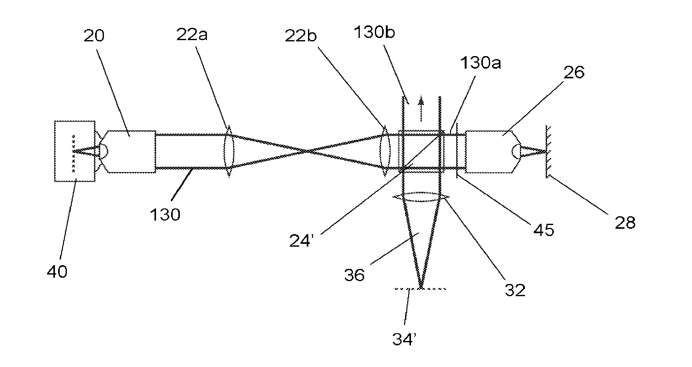
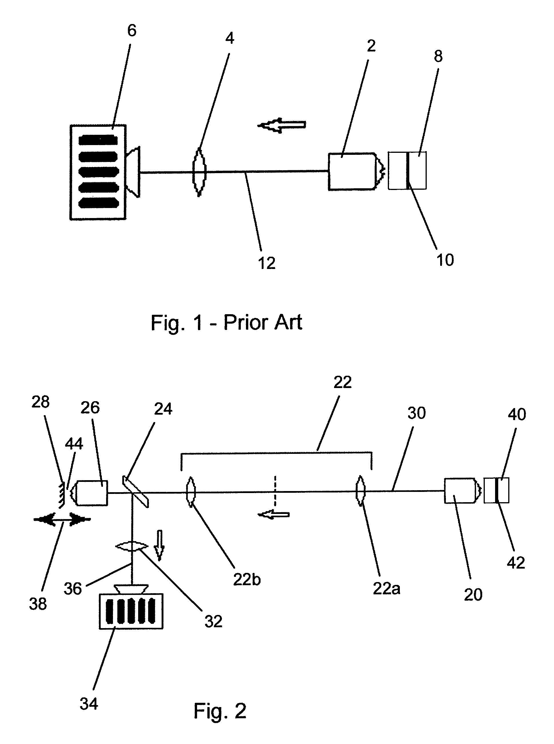
[0043]In the invention shown in FIG. 2, the microscope system includes an objective lens 20, a mapping lens system 22, beam splitter 24, a reference lens 26 and a reference mirror 28, all spaced along a first optical axis 30. The objective lens 20 and the reference lens 26 are identical high NA lenses. An imaging lens 32 (or “tube” lens) and a CCD detector 34 are spaced along a second optical axis 36 that intersects the first optical axis 30 at right angles where it passes through the beam splitter 24.

[0044]The mapping lens system 22 is a 4f system comprising two lenses 22a,22b, each of which has a focal length f and is spaced from the other one of the two lenses by a distance 2f, and from the pupil plane of the adjacent one of the objective lens 20 and the reference lens 26 by a distance f. The mapping lens system 22 maps the wavefront appearing at the pupil plane of the objective lens 20 onto the pupil plane of the reference lens 26.

[0045]The reference mirror 28 is mounted on a pi...

third embodiment

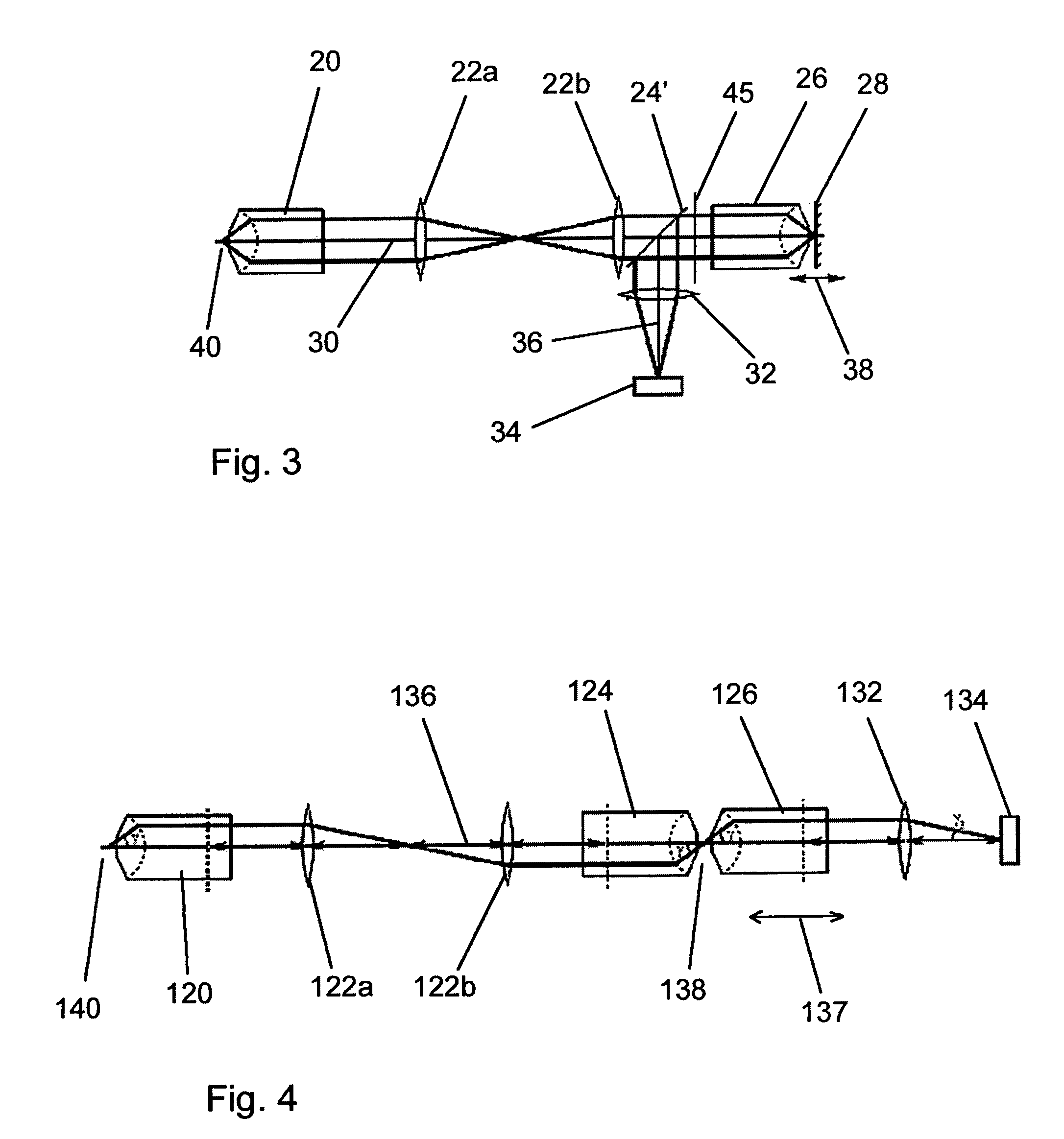
[0051]the invention is shown in FIG. 4. In this embodiment, the microscope system includes an objective lens 120, a mapping lens system 122a,b, a first reference lens 124, a second reference lens 126, an imaging lens 132 and a CCD detector 134, all spaced along an optical axis 136. The mapping lens system 122 maps the wavefront appearing at the pupil plane of the objective lens 120 onto the pupil plane of the first reference lens 124. The objective lens 120 and the first and second reference lenses 124,126 are identical or matched high NA lenses.

[0052]The second reference lens 126 is mounted so as to be moveable relative to the first reference lens 124 along the optical axis 136, and is attached to a piezo transducer (not shown) that allows its position relative to the first reference lens 124 to be adjusted rapidly as indicated by arrow 137.

[0053]Light from a specimen is collected by the objective lens 120 and mapped by the mapping lens system 122 onto the pupil plane of the first ...

seventh embodiment

[0077]FIG. 8 illustrates a slit scanning confocal microscope according to the invention. The microscope includes a laser light source 510, a beam expander 512, a cylindrical lens 514 and a narrow slit 516, which together form a flat beam of light, which is focused by a lens 518 into a reference lens 520. This light is focused by the reference lens 520 into an intermediate image space 521 adjacent a reference mirror 522, which is mounted for movement along the optical axis 524 of the aforesaid components. The light is reflected back into the reference lens 520 by the mirror 522 and then reflected along a second optical axis 526 by a beam splitter 528. This light is focused through an intermediate lens system 530 into an objective lens 532, which focuses the flat light beam onto a specimen 534.

[0078]The axial position at which the light beam is focused within the specimen 534 can be adjusted by moving the reference mirror 522. The objective lens 532 and the reference lens 520 are matc...


PUM


Abstract

A focusing apparatus for use with an optical system having a high NA objective lens includes an image forming and capturing apparatus for forming an image in an intermediate image zone, and for capturing an image by receiving and refocusing light from a selected focal plane within the intermediate image zone, and a focus adjusting apparatus for adjusting the position of the selected focal plane within the intermediate image zone. The image forming and capturing apparatus includes at least one high NA lens. In use, spherical aberration introduced by the high NA objective lens is reduced.

Description

RELATED APPLICATIONS[0001]This application is the U.S. National phase filing under 35 U.S.C. §371 of PCT / GB2007 / 004916, filed Dec. 20, 2007, which designated the United States and was published in English, which claims priority under 35 U.S.C. §(a)-(d) to Great Britain Patent Application No. 0625775.2, filed Dec. 22, 2006. The contents of these applications is incorporated herein by reference in their entireties.FIELD OF THE INVENTION[0002]The present invention relates to a focusing apparatus and method and in particular, but not exclusively, to a focusing apparatus and method for use in microscopic applications. The invention may also have various non-microscopic applications.BACKGROUND OF THE INVENTION[0003]The term “microscopic” as used herein refers to optical applications having a resolution in the range of approximately 10−4 to 10−7 meter. Such applications are generally characterized by the use of high numerical aperture (NA) objective optics, typically with a NA in the range...

Claims


Application Information

Patent Timeline
Patent Type & Authority Patents(United States)
IPC IPC(8): G02B21/00
CPCG02B21/006G02B21/241G02B21/245G02B21/04G02B27/283G02B21/24G02B21/361
Inventor WILSON, TONYJUSKAITIS, RIMVYDASBOOTH, MARTIN JAMESBOTCHERBY, EDWARD
Owner OXFORD UNIV INNOVATION LTD
Why Eureka
Try Eureka