Operation of a three level converter

a converter and three-level technology, applied in the field of three-level converters, can solve the problems of low overall efficiency of pv systems, poor efficiency of power electronic converters used in photovoltaic systems, and high power loss of diode clamped multi-level converters

Active Publication Date: 2012-03-27
GENERAL ELECTRIC CO
View PDF7 Cites 35 Cited by
  • Summary
  • Abstract
  • Description
  • Claims
  • Application Information

AI Technical Summary

Problems solved by technology

In general, the efficiency of power electronic converters used in photovoltaic systems is poor at partial load and high at medium to full load.
Since the converters operate at partial load most of the time, overall efficiency of the PV systems is less than optimal.
Hence, power losses of diode clamped multilevel converters are an important issue in unit sizing photovoltaic systems because of the influence of such losses on the total energy delivered to the load.
Power losses occur in diode clamped converters mainly because of losses in switching devices such as Insulated Gate Bipolar Transistors (IGBTs), Gate Turn Off (GTO) Thyristors, Integrated Gate Commuted Thyristors (IGCTs) and diodes which are generally used in the converters or passive components such as filter inductors.
The switching devices generally have three major types of losses: conduction losses, switching losses, and gate drive losses.
However, conduction losses and switching losses are very much part of the diode losses.
Losses in fast switching diodes are typically higher than slow switching diodes.
The conduction losses correspond to losses that occur in the switching device during its conduction (when the device is carrying a current).
Filter inductor losses consist typically of copper and iron losses.
Copper losses in power converters are typically increased by skin and proximity effects.

Method used


Image

  • Operation of a three level converter
  • Operation of a three level converter
  • Operation of a three level converter

Examples


Embodiment Construction

[0016]As discussed in detail below, embodiments of the present invention function to provide a system and a method for efficient power transfer from a solar power generation system to a load or a power grid.

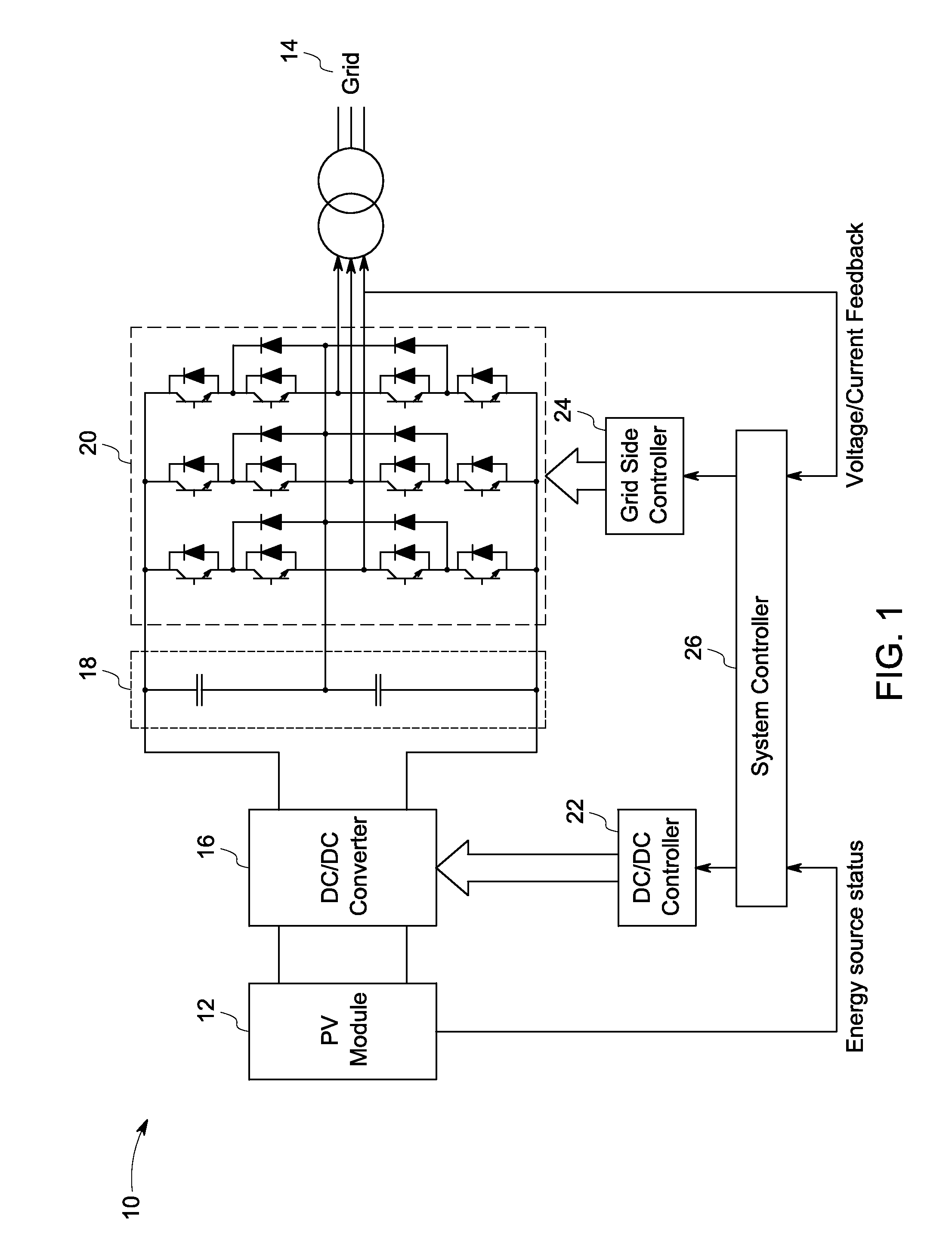
[0017]FIG. 1 illustrates a solar power generation system 10. The power generation system includes a PV module 12. The PV module is connected to a power grid 14 through a DC / DC converter 16, a DC link 18 and a grid side three-phase three level DC / AC converter 20. The DC / AC converter 20 maintains a constant DC voltage at the DC link 18, and thus the energy flow from the DC link 18 to the power grid 14 is managed. The DC / DC converter 16 is controlled by a DC / DC controller 22, and the grid side converter 20 is controlled by a grid side controller 24. A system controller 26 generates a reference DC voltage command for the DC / DC converter 22 and a reference output voltage magnitude command and a reference frequency command for the grid side converter 24. In one embodiment, the PV modul...


PUM


Abstract

A method of operating a three level converter includes controlling the output voltage of the converter when a DC link voltage of the three level converter is lower than one-half of a rated DC link voltage of the converter by, for each leg of the converter, alternately connecting an output terminal of the leg to the positive terminal or the negative terminal of the DC link. When the DC link voltage is at least one-half of the rated DC link voltage, the method includes controlling the output voltage of the converter by, for each leg, selectively connecting the output terminal of the converter to the positive terminal, the negative terminal, or a mid-point of the DC link.

Description

BACKGROUND[0001]This invention relates generally to electric energy conversion, and, more specifically, to efficient connection of a photovoltaic module to a power grid or a load.[0002]With the rising cost and scarcity of conventional energy sources and concerns about the environment, there is a significant interest in alternative energy sources such as solar power and wind power. Solar power generation uses photovoltaic (PV) modules to generate electricity from the sun. Multiple PV cells are connected electrically to one another in such systems. The electricity generated by PV modules is transmitted to the power grid through one or multiple power electronic converters such as diode clamped converters.[0003]In general, the efficiency of power electronic converters used in photovoltaic systems is poor at partial load and high at medium to full load. Since the converters operate at partial load most of the time, overall efficiency of the PV systems is less than optimal. Hence, power l...

Claims


Application Information

Patent Timeline
Patent Type & Authority Patents(United States)
IPC IPC(8): H02M7/487
CPCH02M7/487Y10S323/906H02M7/5395
Inventor EL-BARBARI, SAID FAROUK SAIDROESNER, ROBERTSHEN, JIE
Owner GENERAL ELECTRIC CO
Why Eureka
Try Eureka