Fixing device and image formation apparatus

a fixing device and image technology, applied in the direction of electrographic process apparatus, instruments, optics, etc., can solve the problems of uneven glossiness, thermal damage or deterioration of components positioned in the vicinity of said contactless portions, and the inability to easily transfer heat, etc., to achieve the effect of reducing the heat capacity of a heat generation member, reducing the length of the belt and saving energy

Inactive Publication Date: 2012-03-27
KONICA MINOLTA BUSINESS TECH INC
View PDF13 Cites 24 Cited by
  • Summary
  • Abstract
  • Description
  • Claims
  • Application Information

AI Technical Summary

Benefits of technology

[0018]The present invention aims to provide a fixing device that (i) has a self-temperature control function with the aid of a magnetic shunt alloy, (ii) reduces heat capacity of a heat generation member as compared to conventional technologies, (iii) effectively conserves energy, and (iv) promptly executes the warm-up. The present invention also aims to provide an image formation apparatus comprising such a fixing device. In particular, the present invention aims to provide a fixing device having a self-temperature control function even when a base member for a fixing belt is made of a conductive material that is not a magnetic shunt alloy, and an image formation apparatus comprising such a fixing device.

Problems solved by technology

With the above structure, however, only a small area of the heat generation member is in contact with other components, with the result that the heat cannot easily be transferred.
This may thermally damage or deteriorate components positioned in the vicinity of said contactless portions.
Also, in a case where a print job to print on a recording sheet having a large width (hereinafter, “large-sized sheet”) is executed immediately after the aforementioned repetition of the print job to print on the small-sized sheet, several defects such as hot offset and uneven glossiness appear on the outer edges of the large-sized sheet in the width direction thereof.
The fixing belt in this document has a significantly small heat capacity, rendering a warm-up period extremely short.
This is not suitable for energy conservation.
Furthermore, if the fixing device cannot perform the warm-up promptly, the user will have to wait for a while after turning on the power of the image formation apparatus, which is not favorable.
However, it is not easy to manufacture a fixing belt having a magnetic shunt alloy layer of a uniform thickness.
It is not impossible to manufacture such a fixing belt, but it would be difficult for such a fixing belt to have all the essential properties (e.g., temperature characteristics and strength) it should have.
Such a fixing belt could be extremely costly as well.
However, when a conductive material that is not a magnetic shunt alloy is provided as the base member of the fixing belt to serve as a conductive heat generation layer, it is considered that the stated self-temperature control function is difficult to realize using conventional technologies, unlike a case where a conductive material is provided as one of constituents of the fixing belt for assisting the fixing belt in generating heat.

Method used


Image

  • Fixing device and image formation apparatus
  • Fixing device and image formation apparatus
  • Fixing device and image formation apparatus

Examples


embodiment 1

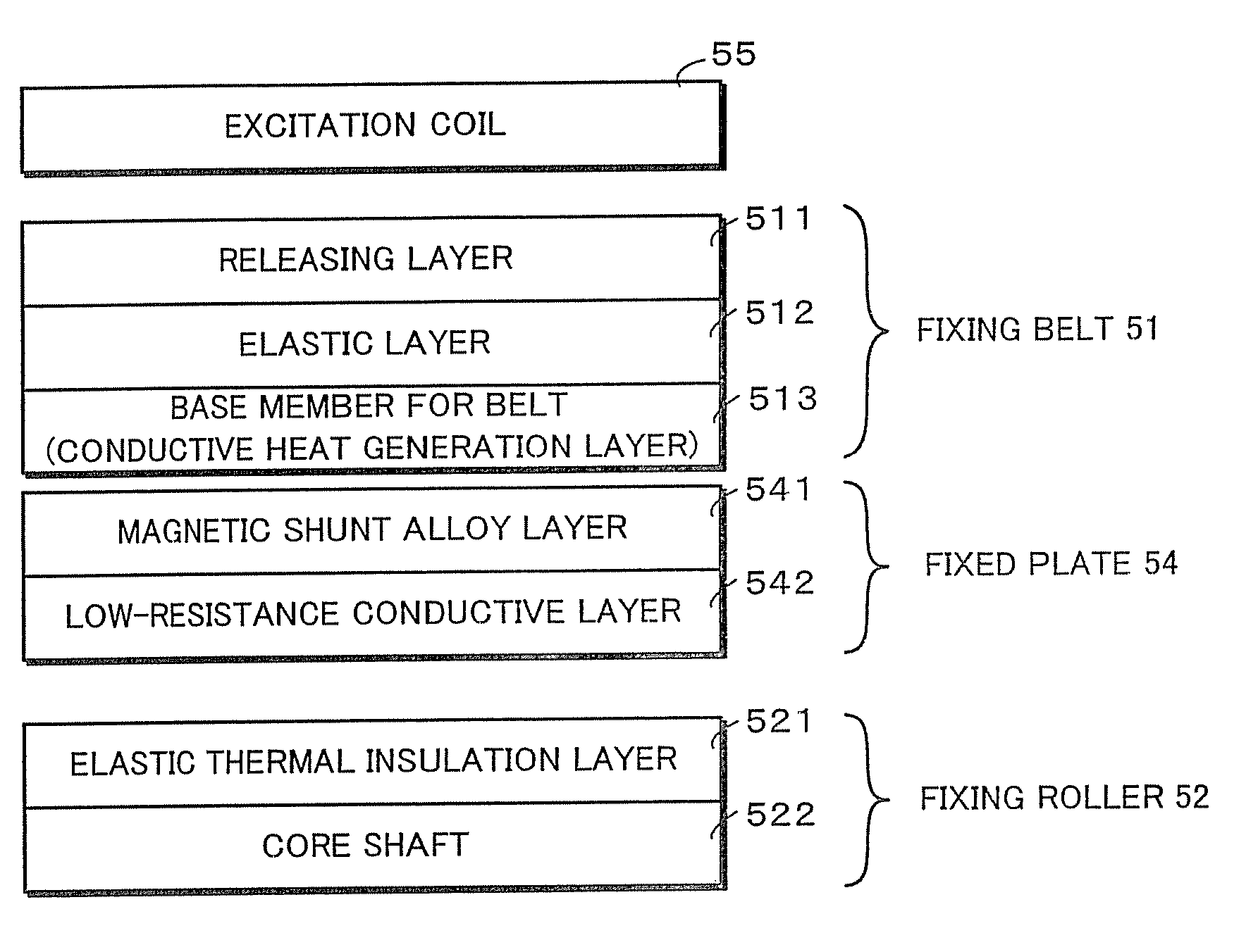
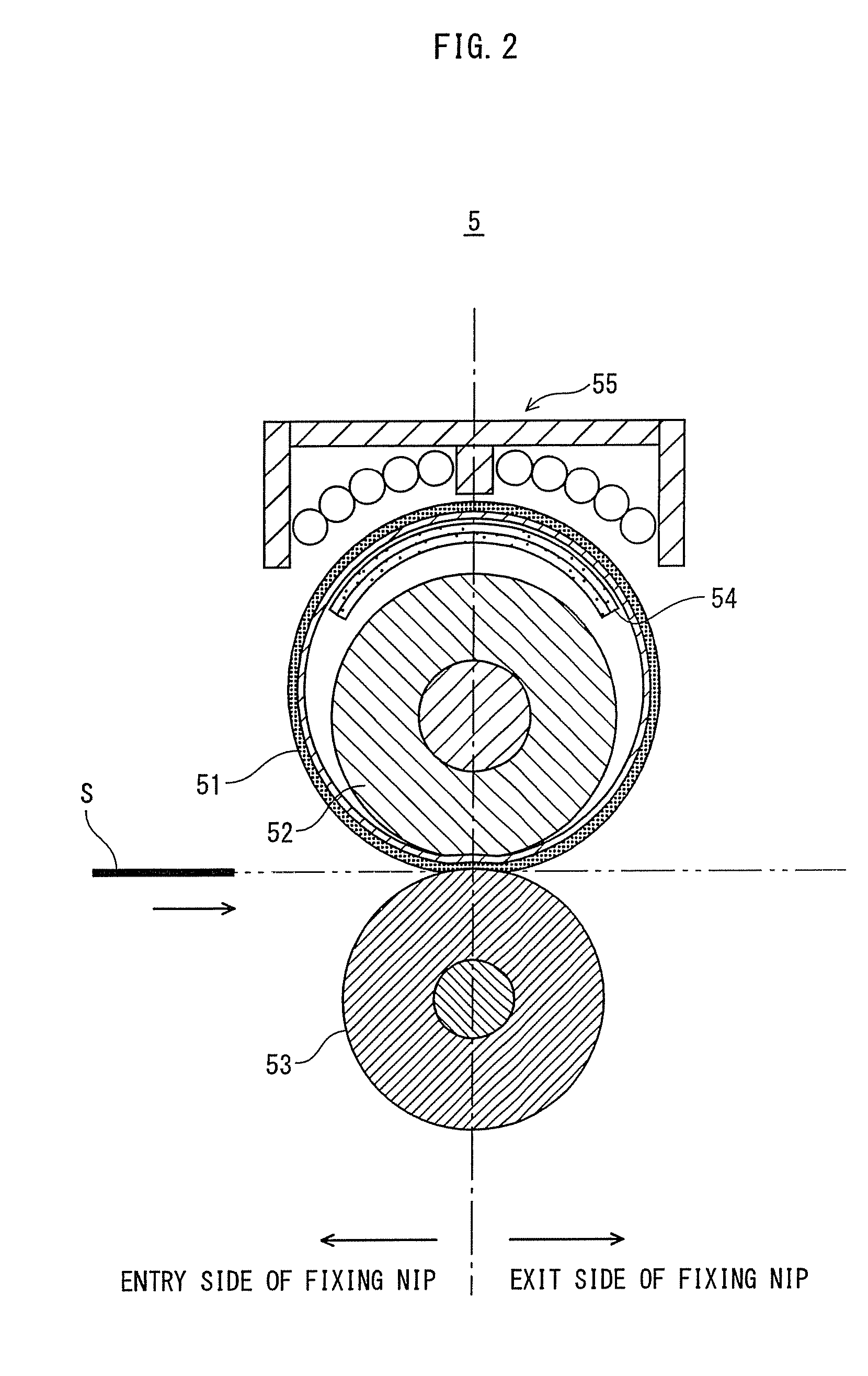
[0050]Embodiment 1 introduces an image formation apparatus comprising a fixing device that thermally fixes an unfixed image onto a recording sheet by using a heat source of an induction heating type. In the fixing device, a thin film made of nickel is used as a base member for a fixing belt, the base member functioning as a conductive heat generation layer. A fixed plate, which is formed by layering a magnetic shunt alloy layer and a conductive layer, is positioned inside the inner circumference of the fixing belt, in such a manner that the fixed plate faces an excitation coil with the fixing belt in between. Here, the thickness of each layer, as well as the frequency at which magnetic flux generated by the excitation coil is reversed, are respectively set at proper values, in order for the fixing device to have a self-temperature control function, reduce heat capacity of a heat generation member, effectively conserve energy, and promptly and flawlessly execute the warm-up.

[0051]FIG...


PUM


Abstract

A fixing device forms a fixing nip by pressing a first roller, which is inside a rotation path of a rotating belt, with a second roller via the belt, and thermally fixes an unfixed image formed on a sheet S by passing the sheet S through the fixing nip while heating the belt by electromagnetic induction. The fixing device comprises an excitation coil positioned outside said path, and a fixed plate that (i) is inside said path, substantially facing the excitation coil via the belt, (ii) contacts an inner surface of the belt, and (iii) keeps the belt on said path. A base member of the belt is a conductive heat generation layer containing no magnetic shunt alloy. The fixed plate includes a conductive layer and a magnetic shunt alloy layer that is closer to the belt than the conductive layer.

Description

[0001]This application is based on application No. 2008-160575 filed in Japan, the content of which is hereby incorporated by reference.BACKGROUND OF INVENTION[0002](1) Field of the Invention[0003]The present invention relates to an image formation apparatus comprising a fixing device, and in particular to technology for, when performing thermal fixing on a small-sized recording sheet by using an induction heating method, suppressing an excessive temperature increase in portions of a heat generation member that do not come into contact with the small-sized recording sheet.[0004](2) Description of Related Art[0005]In recent years, fixing devices that utilize compact heat sources of an induction heating type having a relatively high heat conversion efficiency have been used in some image formation apparatuses of an electrophotographic type, or an electrostatic recording type. Such fixing devices draw great attention due to their abilities to conserve energy, save space, reduce a warm-...

Claims


Application Information

Patent Timeline
Patent Type & Authority Patents(United States)
IPC IPC(8): G03G15/20
CPCG03G15/2057G03G15/2064G03G2215/2029
Inventor MURAKAMI, MASANORIMASUDA, FUMIO
Owner KONICA MINOLTA BUSINESS TECH INC
Why Eureka
Try Eureka