Protective element and secondary battery device

a secondary battery and protection element technology, applied in the field of protection element and secondary battery device, can solve the problems of increasing material cost, low degree of discharge of this type, and long time taken until the blowout of the conductor reliably occurs, so as to prevent uneven distribution of the degree of discharge, reduce environmental burden, and reduce the effect of dispersion

Active Publication Date: 2011-01-20
DEXERIALS CORP
View PDF38 Cites 20 Cited by
  • Summary
  • Abstract
  • Description
  • Claims
  • Application Information

AI Technical Summary

Benefits of technology

[0023]According to the protection element of this invention, a stepped portion for retaining a flux inside of an insulation cover member is provided, thus enabling the flux to be stably retained at a predetermined position. In this manner, in particular, in a case where a flux with its low degree of activity (such as a halogen-free flux) is used, it is possible to prevent uneven distribution of the degree of activity due to the bias of a retention state after coating the flux. Further, dispersion of operation can be extremely reduced in a blowout operation of a soluble conductor, in particular, in characteristics of a heating operation of low power. Moreover, it becomes possible to form a protection element with its small environment burden by employing a halogen-free flux.
[0024]In addition, as set forth in claims 9 and 10, it becomes possible to visually check an appearance of an inside flux by providing an opening on the insulation cover member.
[0025]Further, as set forth in claims 11 and 12, by forming a cutout portion at a retention blowout portion, a void inside of the flux, which occurs at the time of printing, can be released, and can be stably retained at a predetermined position. In particular, in a case where a flux with its low degree of activity (halogen-free) is used, it is possible to prevent uneven distribution of the degree of activity due to the bias of the retention state after coating the flux.
[0026]Furthermore, as set forth in claim 13, a terminal at an electrode side, which is used exclusively for fixing a protection element to a package board, is opened on a baseboard, and the number of electrodes on the baseboard to be connected to the heating element or soluble conductor is limited to three or less, whereby a heat released from the baseboard through the electrodes is restrained, and a blowout time can be reduced.
[0027]Still furthermore, as set forth in claims 14 and 15 and by restraining a board dimensional ratio, there can be provided a protection element which is capable of reducing the heat capacity of a baseboard while maintaining a board strength, reducing a blowout time more significantly than that of the conventional one, and achieving reduction of a height of a protection element, namely which is capable of achieving clashing objectives of reducing a blowout time and achieving reduction of a height of a protection element.
[0028]Yet furthermore, according to a secondary battery device of this invention, a protection element is stably and reliably actuated against an overvoltage / overcurrent; a secondary battery is protected, and accidents such as overheat or firing of a secondary battery can be reliably prevented in advance.

Problems solved by technology

In particular, if a halogen-free flux not containing a halogen component such as bromine (Br) is used in order to mitigate an environmental load, the flux of this type is low in degree of activity, and the state of the flux has greatly influenced the blowout velocity of the soluble conductor.
In such a case, the fused metal of the soluble conductor 3 is prone to flow into a location in which the flux 9 is retained; there emerges a phenomenon that the blowout of the soluble conductor 3 is unlikely to occur at a site which is short of the flux 9; and there has been a problem that extended time is taken until the blowout of the conductor reliably occurs.
Further, in a method of forming a metal pattern on an insulation cover member, of the structure disclosed in Patent Document 1, there is a need to print the metal pattern after molding an insulation cover, and a material cost increases.
Similarly, in the structure disclosed in Patent Document 2 as well, a groove or glass band for preventing spread wetting of a fused alloy must be provided at the periphery of an electrode to which a soluble alloy is connected, which is high in cost.
In addition, in the structure of Patent Document 1, in the event that the insulation cover side causes an abnormality such as a thermal deformation, a metal pattern and the electrode of the insulation cover may be short-circuited due to shortening of a distance from the insulation cover.

Method used


Image

  • Protective element and secondary battery device
  • Protective element and secondary battery device
  • Protective element and secondary battery device

Examples


example 1

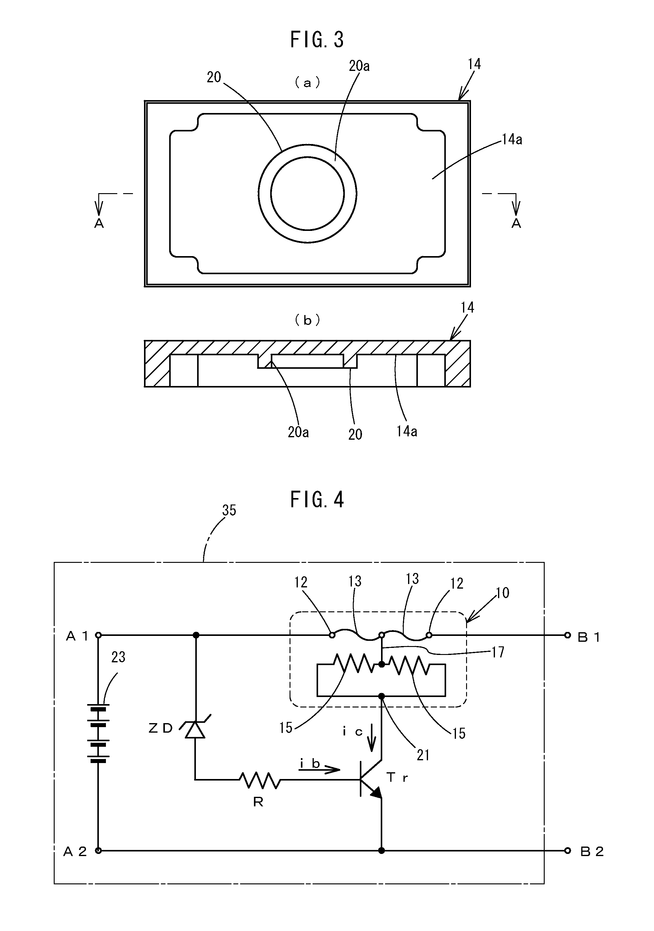
[0096]Next, an example of the protection element of this invention and an operating circuit of a secondary battery device employing the element will be described below. In this example, experiments were carried out by constituting a circuit similar to a power circuit employed in an actual secondary battery device. As to a protection element of a conventional structure, shown in FIG. 28, and a protection element having a cylindrical protrusive stripe on the abovementioned insulation cover member of the first embodiment, comparative experiment of their operation was carried out.

[0097]A protrusion height of the protrusive stripe meets a condition of Formula 1.

B−A≧C  (1)

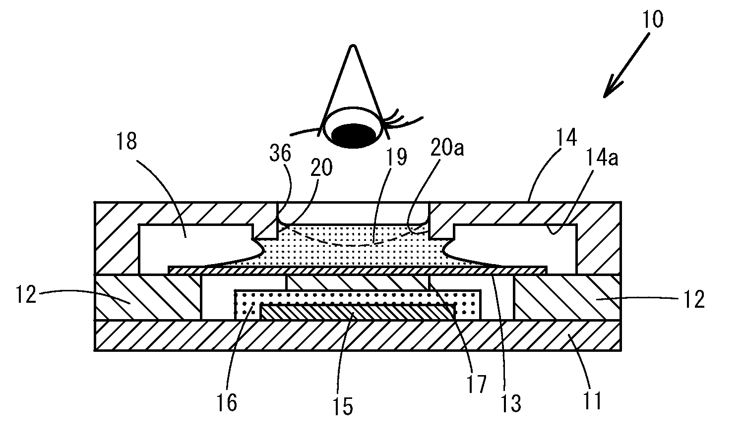
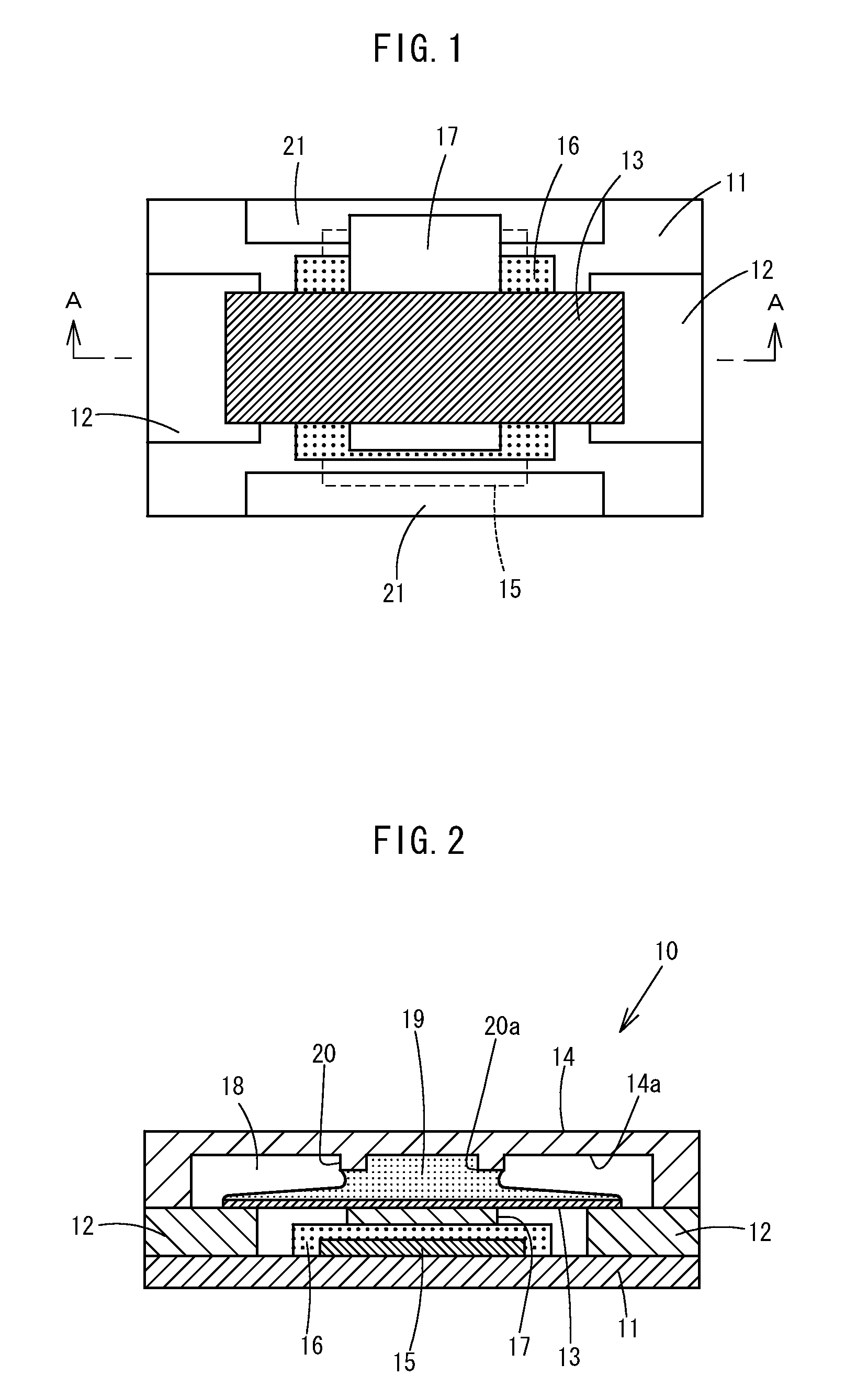
wherein: A denotes a protrusion quantity of a protrusive stripe 20 from an inside top face of an insulation cover member 14; B denotes an interval between a baseboard 11 and the inside top face of the insulation cover member 14; and C denotes a height after blowout of a soluble conductor 13 from the baseboard 11.

[0098]A ...

example 2

[0101]Similarly, table 2 shows results obtained by relatively comparing rates of a blowout time of a structure according to a second embodiment of the invention (the invention 2) while each of MAX, MIN, AVE, and 3σ was defined to be 100%, as to the blowout time of a soluble conductor, in a conventional cover plate structure. A height of a protrusive stripe is equal to that of Example 1. Experiments were carried out at the time of low-power operation of 6 W and at high-power operation of 35 W, and 50 elements were employed in each of the experiments. As a flux, the halogen-containing one was employed.

[0102]In the experimental results as well, a MAX operating time was reduced by 14% at low power, and dispersion (3σ) was reduced by 45%.

TABLE 2Relative comparison of experimental results (N = 50 pcs)Low powerHigh powerPower applied to heating resistor6 W35 WStructure of insulation cover plateTheThePriorinven-Priorinven-arttion 2arttion 2BlowoutMAX100%86%100% 93%time ofMIN100%98%100%106%s...

example 3

[0103]Similarly, table 3 shows results obtained by relatively comparing rates of a blowout time with one another as to the protection elements having had the structure of the protrusive stripe of the first embodiment of the invention (the invention 1) and the structure shown in FIG. 9 of the above-described embodiments while each of MAX, MIN, AVE, and 3σ was defined to be 100%, as to the blowout time of a soluble conductor, in a conventional cover plate structure. Experiments were carried out at low-power operation of 6 W, and 20 elements were employed in each of the experiments. As a flux, the halogen-free one was employed.

[0104]In the experiments, dispersion (3σ) of the blowout time, in a structure in which a protrusive stripe had been provided, became lesser in comparison with that in the conventional structure. In addition, as to the shape of the protrusive stripe, a structure of a cylindrical shape of the first embodiment (the invention 1) showed good results in items of MAX, M...


PUM

PropertyMeasurementUnit
lengthaaaaaaaaaa
lengthaaaaaaaaaa
electric poweraaaaaaaaaa

Abstract

A protection element and a secondary battery device employing the protection element are provided for stably retaining a flux on a soluble conductor at a predetermined position, so as to enable appropriate blowout of the soluble conductor in the event of an abnormality. The protection element has a soluble conductor which is disposed on an insulation baseboard, and which is connected to a power supply path of a device targeted to be protected, and which causes a blowout when a predetermined abnormal electric power, amount is supplied. A flux is coated on a surface of the soluble conductor, and an insulation cover member is mounted on the baseboard and covers the soluble conductor. The protection element also includes a stepped portion for retaining the flux at a predetermined position in contact with the flux, and the stepped portion is formed opposite to the soluble conductor on an interior face of the insulation cover member.

Description

TECHNICAL FIELD[0001]This invention relates to a protection element and a secondary battery device employing the protection element for, in case that an overcurrent or overvoltage is applied, allowing a soluble conductor to cause a blowout due to a heat of such overcurrent or overvoltage, thereby shutting off a current.BACKGROUND ART[0002]Conventionally, a protection element mounted on a secondary battery device or the like is employed as the one having a function of protection from an overvoltage as well as an overcurrent. This protection element is formed so that: a heating element and a soluble conductor made of a low-melting metal are laminated on a board; and the soluble conductor causes a blowout due to an overcurrent, and if an overvoltage occurs as well, power is supplied to the heating element in the protection element, and the soluble conductor causes a blowout due to a heat of the heating element. The blowout of the soluble conductor is due to the goodness of wettability ...

Claims


Application Information

Patent Timeline
Patent Type & Authority Applications(United States)
IPC IPC(8): H01H71/20H01H85/00H01M50/583
CPCY10T29/49107H01M10/4235H01M10/0525H01M2/34H01H37/761Y02E60/10H01H2085/466H01H61/02H01M50/583
Inventor KIMURA, YUJIASADA, TAKAHIROYONEDA, YOSHIHIROSUZUKI, KAZUAKI
Owner DEXERIALS CORP
Why Eureka
Try Eureka