Image forming apparatus

a technology of forming apparatus and forming chamber, which is applied in the direction of electrographic process apparatus, ohmic resistance heating, instruments, etc., can solve the problems of extending the warm-up time of a member with a large heat capacity, and inadvertently enlarging the entire apparatus, so as to reduce the warm-up time, promote the effect of reducing the heat capacity and saving spa

Active Publication Date: 2009-07-09
KYOCERA DOCUMENT SOLUTIONS INC
View PDF17 Cites 20 Cited by
  • Summary
  • Abstract
  • Description
  • Claims
  • Application Information

AI Technical Summary

Benefits of technology

[0009]An object of the present invention is to provide an image forming apparatus capable of promoting lower heat capacity, reducing a warm-up time and realizing space saving by reducing the number of members arranged in a heating member.

Problems solved by technology

However, the first prior art has a problem of inadvertently enlarging the entire apparatus since the movable range of the magnetic member is large and an extra space is, accordingly necessary.
However, the interior of the heating roller is a high-temperature environment and it is necessary to set a high Curie temperature in the case of arranging a certain member therein.
Above all, a member with large heat capacity has a problem of extending a warm-up time.

Method used


Image

  • Image forming apparatus
  • Image forming apparatus
  • Image forming apparatus

Examples


first embodiment

of the Fixing Unit

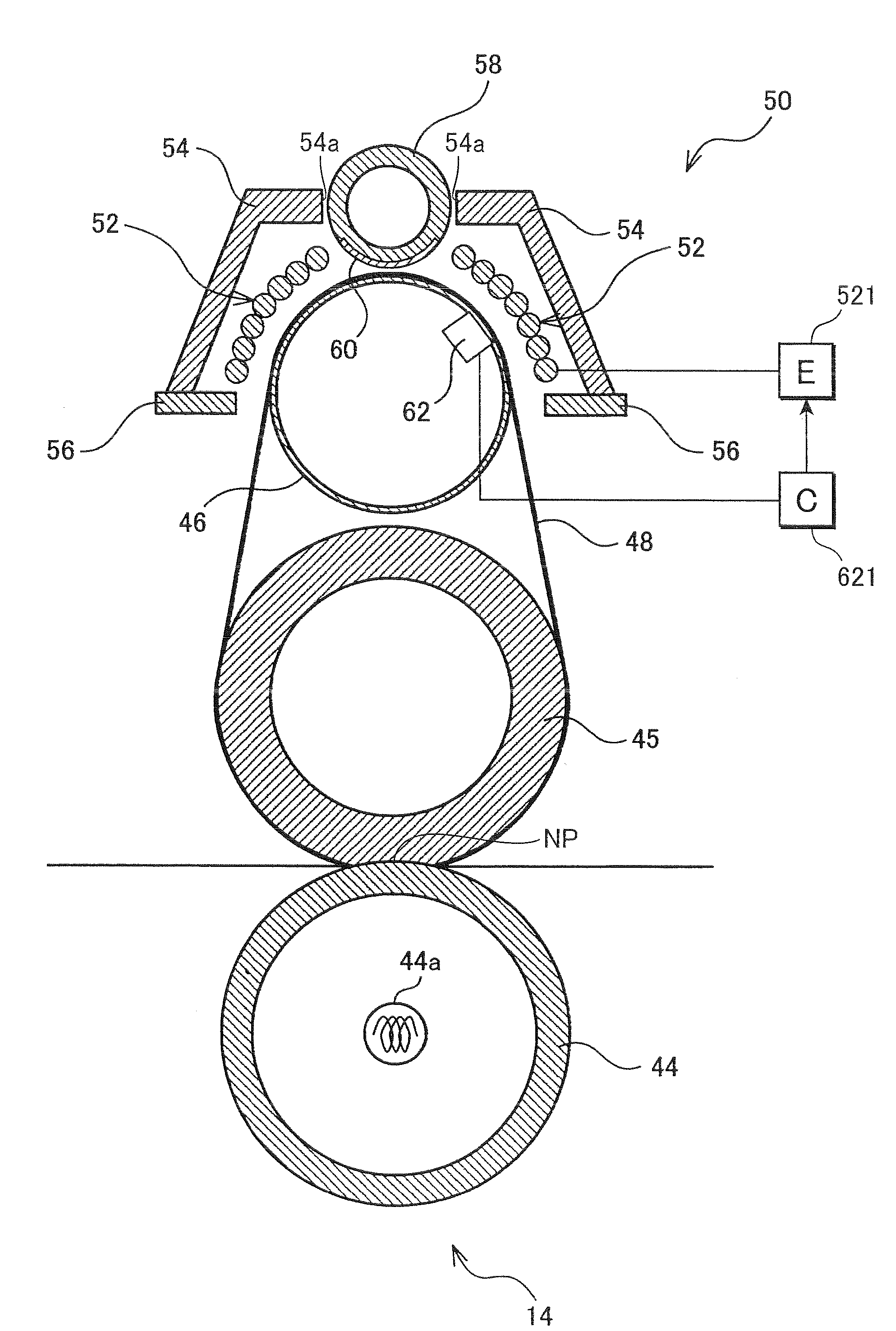
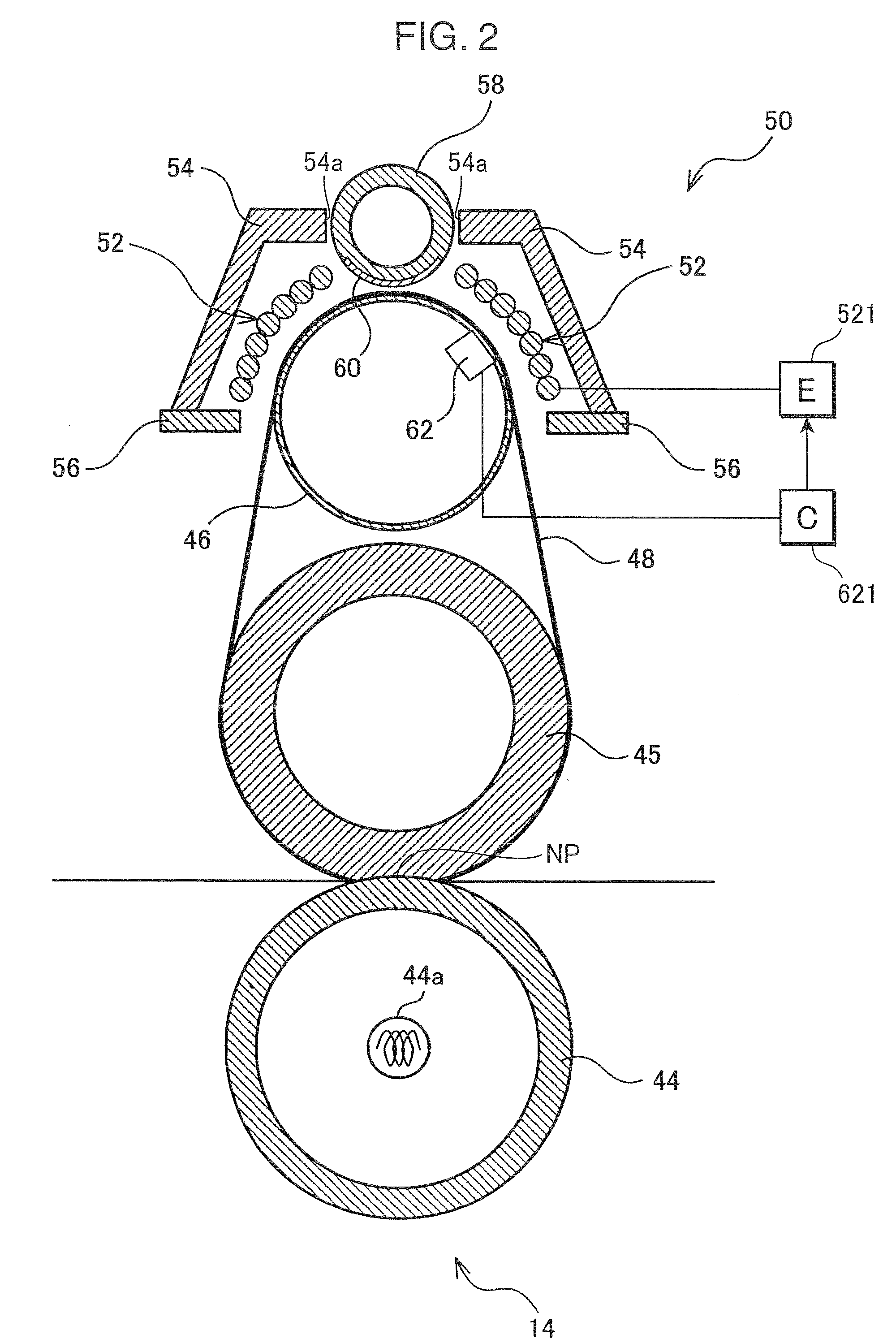
[0052]Next, the fixing unit 14 according to a first embodiment employed in the above image forming apparatus 1 is described in detail.

[0053]FIG. 2 is a vertical section showing the structure of the fixing unit 14 of the first embodiment. In a state shown in FIG. 2, the orientation of the fixing unit 14 is rotated counterclockwise by about 90° from an actually mounted state in the image forming apparatus 1. Accordingly, the sheet conveying direction from lower side to upper side in FIG. 1 is from right side to left side in FIG. 2. If the apparatus main body 2 has a larger size (complex machine or the like), the fixing unit 14 may be actually mounted in the orientation shown in FIG. 2.

[0054]The fixing unit 14 includes the pressure roller 44, the fixing roller 45, the heat roller 46 and the heating belt 48 as described above. The pressure roller 44 is made of a metal, but the fixing roller 45 includes the elastic layer of silicon sponge on the outer layer. Thus, a fla...

second embodiment

of the Fixing Unit

[0087]FIG. 9 is a vertical section showing the structure of a fixing unit 214 according to a second embodiment. The fixing unit 214 includes a pressure roller 44, a fixing roller 45, a heat roller 46 and a heating belt 48 as in the above fixing unit 14. Since these members are similar to those of the first embodiment, they are not described here.

[0088]The fixing unit 214 further includes an IH coil unit 250 at an outer side of the heat roller 46 and the heating belt 48. The IH coil unit 250 includes an induction heating coil 52 (coil), a pair of arch cores 54 (part of a first core), a pair of side cores 56 (part of the first core) and a center core 258 (second core). Shielding members 260 are mounted along the outer surface of the center core 258. Since the fixing unit 214 of the second embodiment substantially differs from the fixing unit 14 of the first embodiment only in the shielding members 260 provided in this center core 258, the following description is cen...

first modification

[First Modification]

[0135]FIG. 26 is a diagram showing a fixing unit 214A according to a first modification of the second embodiment. In this fixing unit 214A, a toner image is fixed by the fixing roller 45A and the pressure roller 44 without using the above heating belt 48. The IH coil unit 250 is arranged to face the circumferential surface of this fixing roller 45A.

[0136]A magnetic body similar to that of the above heating belt is, for example, wound around the outer circumferential surface of the fixing roller 45A, and the magnetic body is induction heated by the induction heating coil 52. In this case, the thermistor 62 is disposed at a position outside the fixing roller 45A to face a magnetic body layer. The other construction is similar to the above and the shielding members 260B can be moved to the shielding positions and the retracted positions by rotating the center core 58.


PUM


Abstract

An image forming apparatus has an image forming station and a fixing unit. The fixing unit includes a coil for generating a magnetic field for induction heating the heating member. A first core made of a magnetic material is arranged fixedly around the coil. A second core made of a magnetic material is between the first core and the heating member in a generation direction of the magnetic field to form a magnetic path in cooperation with the first core and capable of changing a posture thereof. A shield made of a nonmagnetic metal is arranged along the outer surface of the second core to shield magnetism in the magnetic field and a magnetic shielding portion for changing the posture of the second core between a first posture where the shield shields the magnetism and a second posture where the shield does not shield the magnetism.

Description

BACKGROUND OF THE INVENTION[0001]1. Field of the Invention[0002]The present invention relates to an image forming apparatus provided with a fixing unit for permitting a sheet bearing a toner image to pass between a heating member and a pressing member to heat and melt unfixed toner and fixe it to the sheet.[0003]2. Description of the Related Art[0004]In recent years, attention has been focused of belt-type image forming apparatuses, in which a smaller heat capacity can be set, due to demands of shortening a warm-up time and saving energy in a fixing unit (see, for example, Japanese Unexamined Patent Publication No. H06-318001). Attention has been also focused on an electromagnetic induction heating method (IH) with a possibility of quick heating and high efficiency heating in recent years, and many products as a combination of electromagnetic induction heating and the employment of a belt have commercialized in light of saving energy upon fixing a color image. In the case of combini...

Claims


Application Information

Patent Timeline
Patent Type & Authority Applications(United States)
IPC IPC(8): G03G21/20G03G15/20
CPCG03G15/2007G03G15/2039G03G2215/2032
Inventor NANJO, YUZURUNAKAJIMA, EIJIKONDO, AKIHIROISHIDA, NAOYUKIGON, SYOUKOUKASAMA, KENICHI
Owner KYOCERA DOCUMENT SOLUTIONS INC
Why Eureka
Try Eureka