Gas sensor element and gas sensor

a gas sensor and element technology, applied in the field of gas sensor element and gas sensor, can solve the problems of increasing the standby time until detection, increasing the power consumption of the gas sensor element b>1000/b> by the heater b>1200, h, etc., and achieving the effect of reducing the power consumption of heating and restrainting the occurrence of cracks

Active Publication Date: 2016-02-25
NGK SPARK PLUG CO LTD
View PDF5 Cites 20 Cited by
  • Summary
  • Abstract
  • Description
  • Claims
  • Application Information

AI Technical Summary

Benefits of technology

[0021]According to the present invention, it is possible to reduce power consumption in heating the gas sensor element having the porous protection layer by the heater and standby time until initiation of detection, and to restrain occurrence of cracking as a result of adhesion of water to a solid electrolyte body.

Problems solved by technology

However, when the porous protection layer 1400 is provided at a forward end portion of the gas sensor element 1000, heat capacity of the porous protection layer 1400 and, in turn, heat capacity of the entire gas sensor element 1000, increases, thereby raising the problem of an increase in power consumption in heating the gas sensor element 1000 by the heater 1200h and an increase in standby time until initiation of detection.

Method used


Image

  • Gas sensor element and gas sensor
  • Gas sensor element and gas sensor
  • Gas sensor element and gas sensor

Examples


Embodiment Construction

[0029]An embodiment of the present invention will next be described.

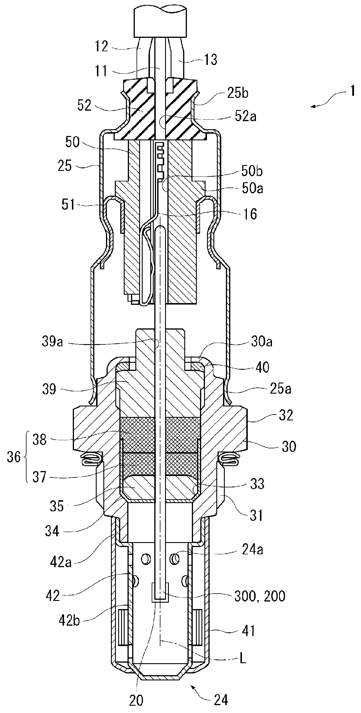
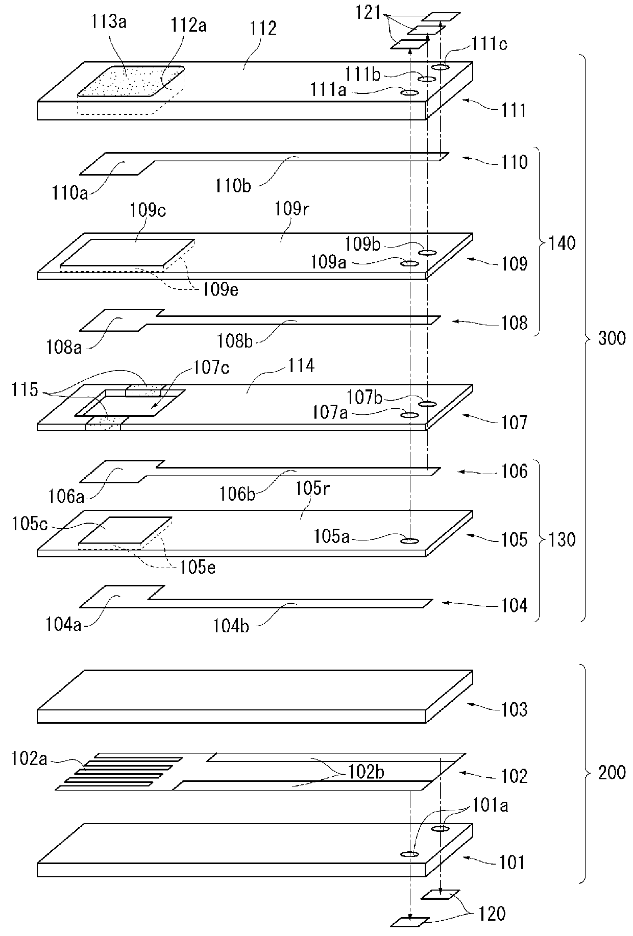
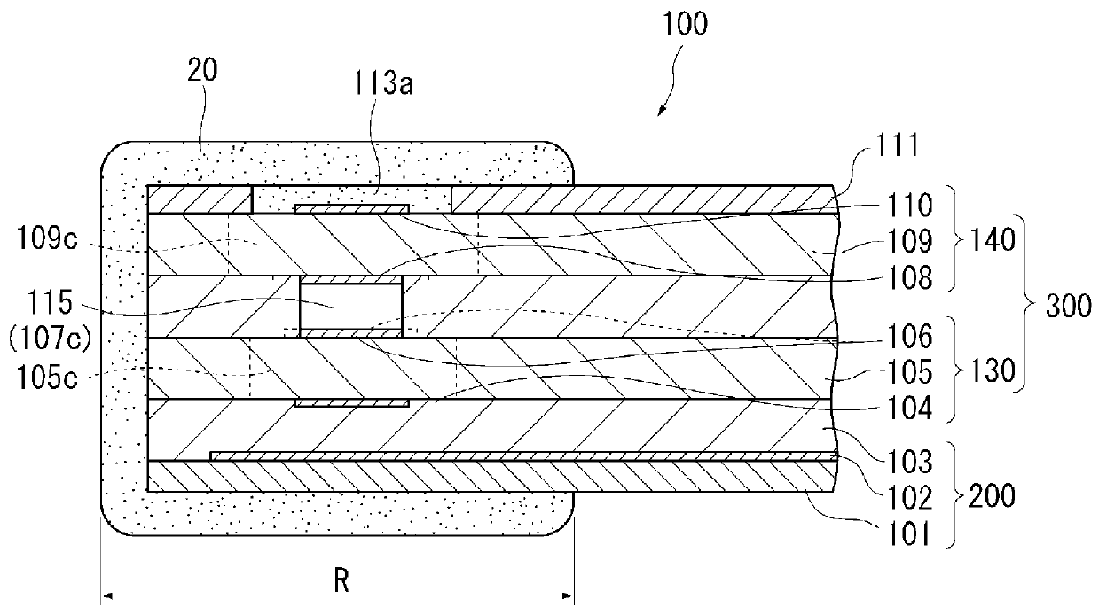
[0030]FIG. 1 is a sectional view of a gas sensor (oxygen sensor) 1 according to the embodiment taken longitudinally (along an axis L); FIG. 2 is a schematic exploded perspective view showing a detecting element section 300 and a heater section 200; FIG. 3 is a sectional view of a gas sensor element 100 taken along the axis L.

[0031]As shown in FIG. 1, the gas sensor 1 includes the gas sensor element 100 composed of the detecting element section 300 and the heater section 200 laminated on the detecting element section 300; a metallic shell (corresponding to the “housing” appearing in claims 30 for holding the gas sensor element 100, etc., therein; and a protector 24 attached to a forward end portion of the metallic shell 30. The gas sensor element 100 is disposed in such a manner as to extend along the axis L (in the longitudinal direction).

[0032]As shown in FIG. 2, the heater section 200 includes a first substrate 10...


PUM

PropertyMeasurementUnit
operating temperatureaaaaaaaaaa
temperatureaaaaaaaaaa

Abstract

A gas sensor element includes a laminate formed of a detecting element section and a heater section, and a porous protection layer covering a forward end portion of the laminate. The detecting element section has one or more cells having a solid electrolyte body and a pair of electrodes. The heater section has a heater. Side surfaces of the solid electrolyte bodies in parallel with the direction of lamination are covered with dense insulating members. The cell-to-be-controlled is temperature controlled by the heater to 600° C. to 830° C. The porous protection layer is formed on the laminate from a forward end portion to a region which has a temperature of 500° C. or higher when the temperature control is performed, and the porous protection layer is not formed in a region which has a temperature of 300° C. or lower when the temperature control is performed.

Description

CROSS REFERENCE TO RELATED APPLICATIONS[0001]The present application claims priority to Japanese Patent Application No. 2015-138653, which was filed on Jul. 10, 2015, and Japanese Patent Application No. 2014-170423, which was filed on Aug. 25, 2014, the disclosures of which are herein incorporated by reference in their entirety.BACKGROUND OF THE INVENTION[0002]1. Field of the Invention[0003]The present invention relates to a gas sensor element and a gas sensor used preferably for detecting the concentration of a particular gas contained in, for example, combustion gas or exhaust gas of a combustor, an internal combustion engine, etc.[0004]2. Description of Related Art[0005]Conventionally, a gas sensor is used for detecting the concentration of a particular component (oxygen, etc.) in exhaust gas of an internal combustion engine. As shown in FIG. 6, this gas sensor has a gas sensor element 1000 provided therein. The gas sensor element 1000 includes a laminate of a detecting element s...

Claims


Application Information

Patent Timeline
Patent Type & Authority Applications(United States)
IPC IPC(8): G01N27/407
CPCG01N27/4071
Inventor SAKUMA, SYUNONKAWA, MASAKIOISHI, YUTAFURUTA, NOBUOMIZUTANI, MASAKI
Owner NGK SPARK PLUG CO LTD
Why Eureka
Try Eureka