Hair clipper

a technology of hair clippers and blades, which is applied in the field of hair clippers, can solve the problems of reducing increasing the cost reducing the life of the blade block, so as to maintain the sharpness of cutting blades in a long term, reduce the cost of the replacement blade block, and increase the workability of assembling

Inactive Publication Date: 2012-04-03
MATSUSHITA ELECTRIC WORKS LTD
View PDF21 Cites 16 Cited by
  • Summary
  • Abstract
  • Description
  • Claims
  • Application Information

AI Technical Summary

Benefits of technology

[0008]The present invention is perceived to solve the above mentioned problems of the conventional hair clipper, and an object of the present invention is to provide a hair clipper having a replaceable blade block which enables to maintain the sharpness of cutting of blades in a long term, to reduce the cost of the replaceable blade block, and to increase assemble workability.
[0013]According to such a configuration, since the pressing mechanism is provided on the main body not on the detachable blade block, a number of elements that constitute the replaceable blade block can be decreased, so that assemble workability of the blade block is increased and the cost of the blade block can be decreased. In particular, in the use of barber shop with high frequency of usage or in the medical use where the razor must be disposed essentially, it is possible to reduce the running cost of the replaceable blade block of the hair clipper. Furthermore, since the pressing mechanism is not provided on the blade block, even when the blade block is stocked in a long term, the sharpness of cutting of the blade is never be deteriorated due to fatigue or deformation of the pressing spring. Still furthermore, since the contact portion of the pressing mechanism reciprocally moves in synchronism with the reciprocal motion of the moving blade, the contact portion of the pressing mechanism rarely moves relative to the moving blade, and thus, slipping friction between the contact portion of the pressing mechanism and the moving blade rarely occurs. Consequently, galling or deformation of the element of the pressing mechanism rarely occurs, so that the pressing force of the pressing mechanism is maintained evenly. The sharpness of cutting of the blades becomes stable, and desired sharpness of the cutting blade can be obtained.

Problems solved by technology

Therefore, a number of elements that constitute the replaceable blade block becomes larger, and it causes the reduction of assemble workability and the increase of the cost of the blade block.
Furthermore, when the moving blade is reciprocated frequently, a large friction force occurs between the moving blade and the pressing spring, so that the pressing spring may be galled or deformed due to the friction force, and thereby the life of the blade block may be shortened.
Consequently, the sharpness of cutting by the moving blade and the stationary blade becomes unstable, and desired sharpness of the cutting blade cannot be obtained.
Under such a condition, when the blade block is stocked in a ling term, fatigue and / or deformation of the pressing spring may occur in the term of stock so that it causes the deterioration of the sharpness of cutting.

Method used


Image

  • Hair clipper
  • Hair clipper
  • Hair clipper

Examples


first embodiment

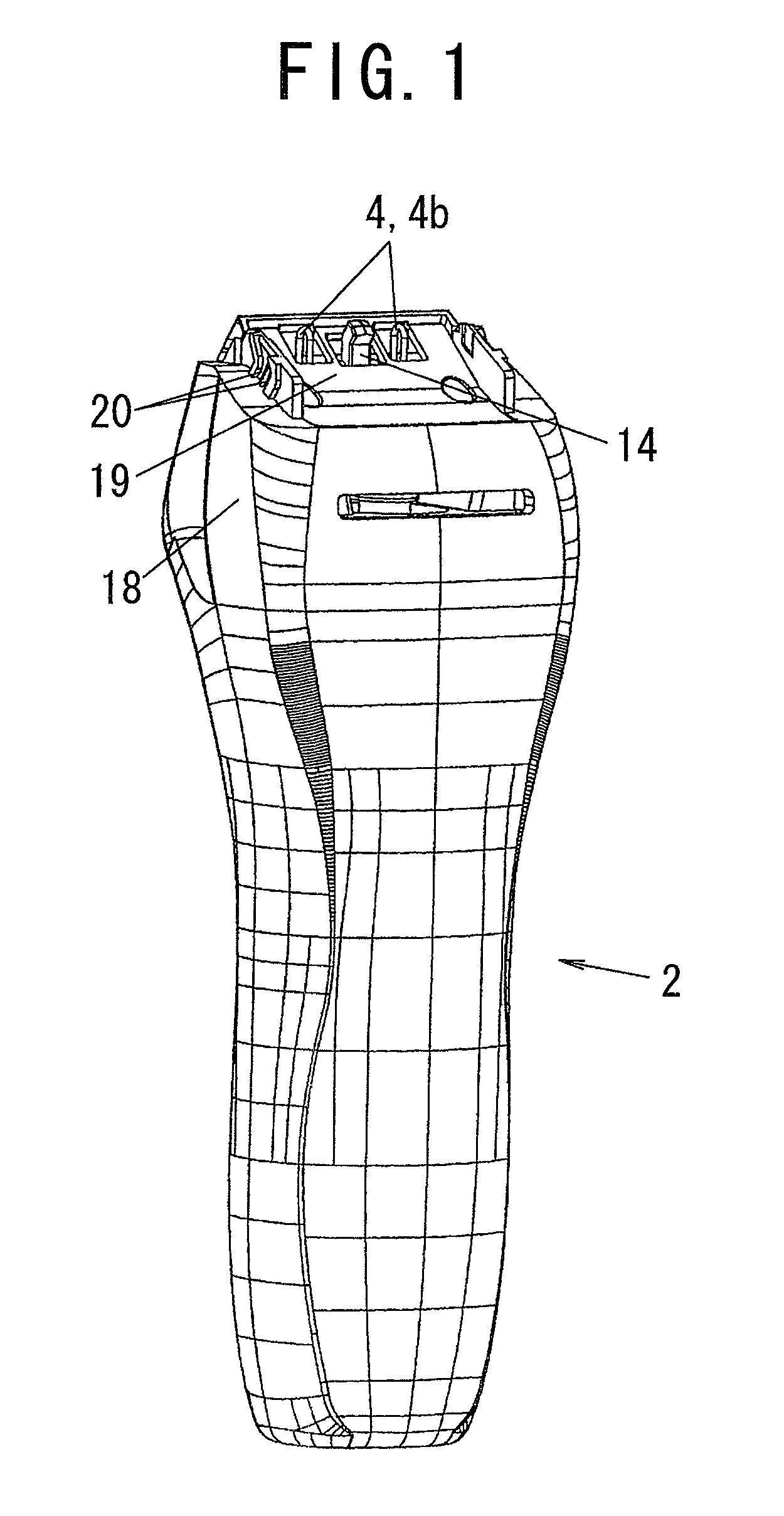
[0053]A hair clipper having a replaceable blade block in accordance with a first embodiment of the present invention is described with reference to the drawings.

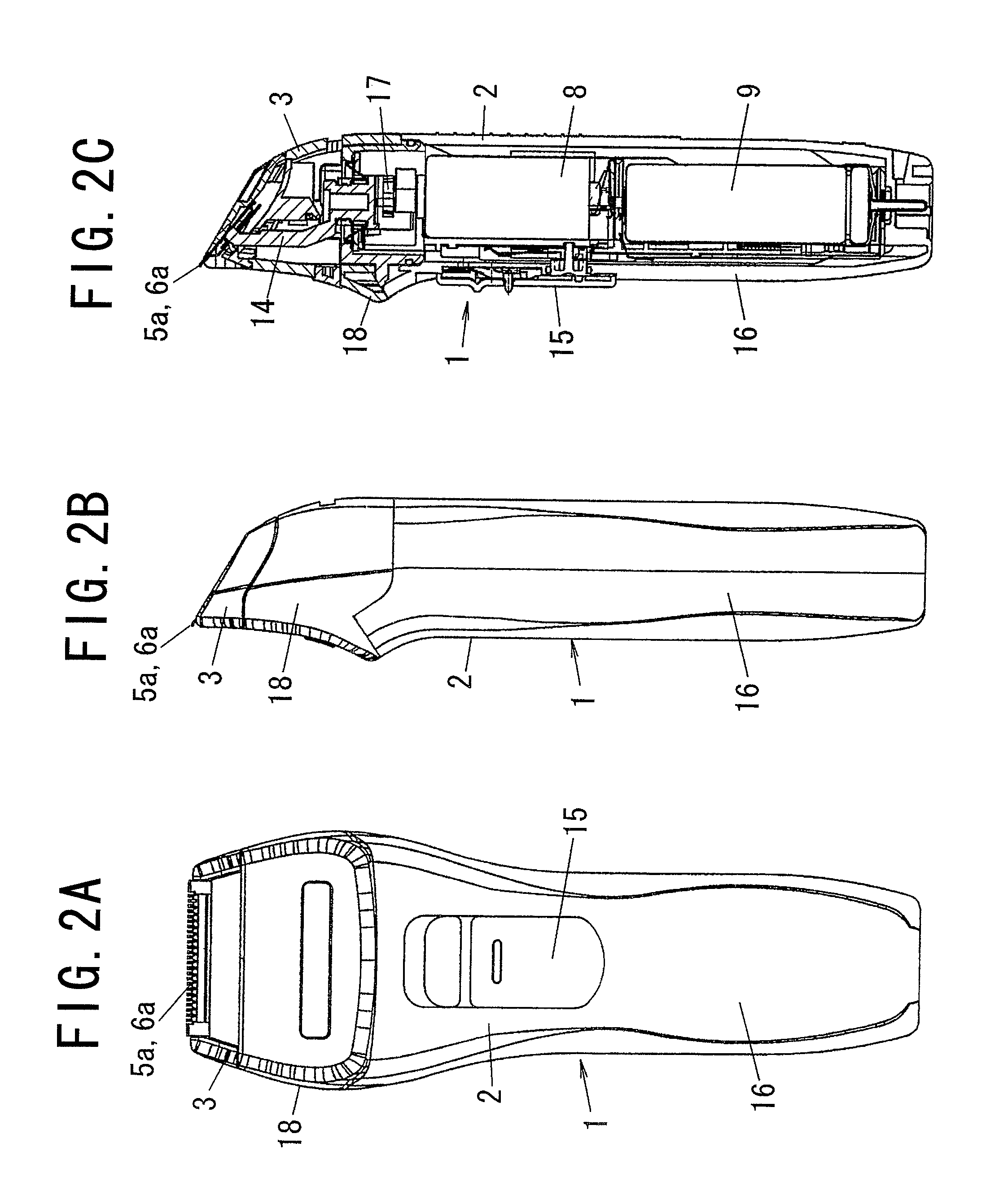
[0054]FIG. 1 shows an appearance of a main body 2 of a hair clipper in the first embodiment. FIGS. 2A and 2B show an entire appearance of the hair clipper 1 with a blade block 3 attached to the main body 2. FIG. 2C shows an inner configuration of the hair clipper 1.

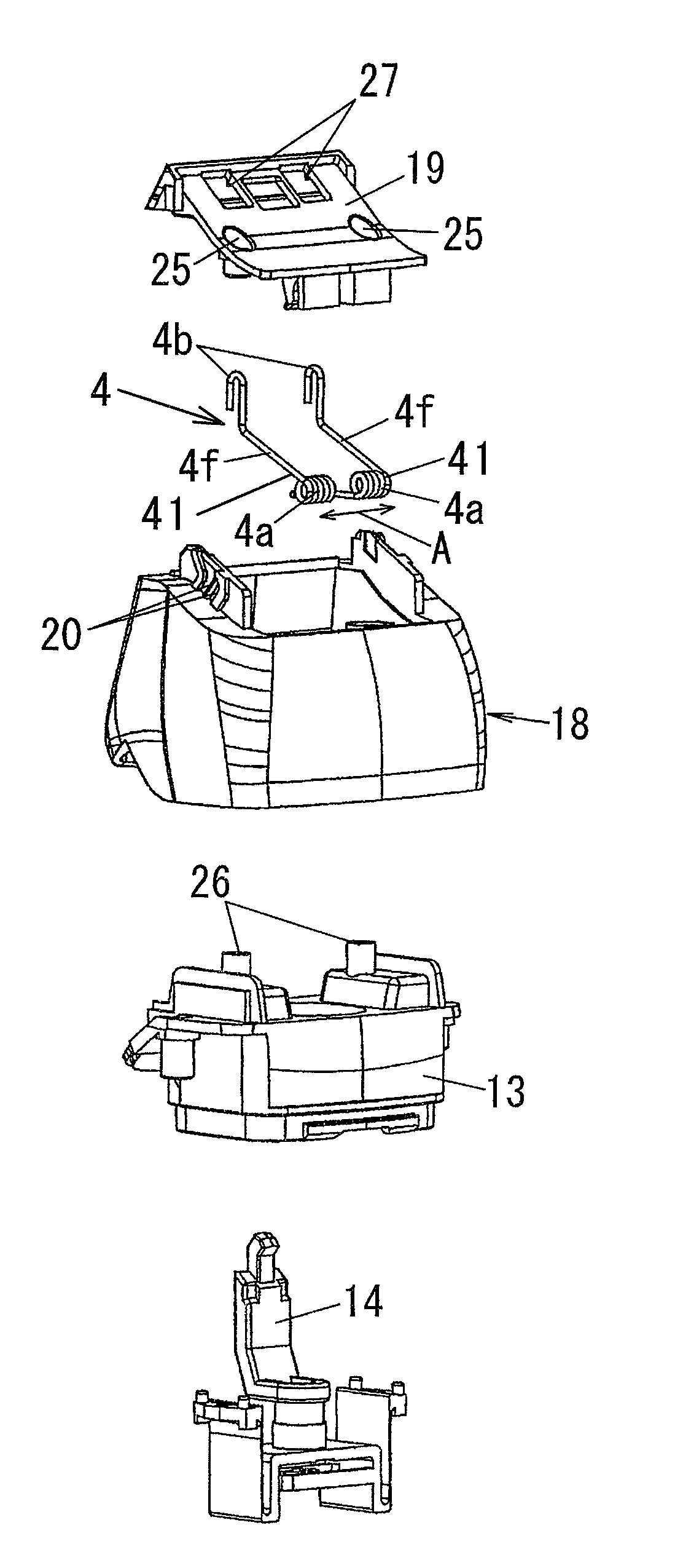
[0055]The hair clipper 1 is comprised of the blade block 3 having a comb-shaped stationary blade 5 and a comb-shaped moving blade 6 to cut hairs, the main body 2 having a driving member 14 which transforms and transmits a driving force of a motor 8 to a reciprocal motion of the moving blade 6, and a pressing mechanism 4 having a pair of contact portions 4b which contact with the moving blade 6 to press the moving blade 6 toward the stationary blade 5. In the first embodiment, the pressing mechanism 4 is comprised of a pair of torsion springs 41, as shown in FIG. 5...

second embodiment

[0077]A hair clipper having a replaceable blade block thereof in accordance with the second embodiment of the present invention are described with reference to FIGS. 17 to 20. In the second embodiment, the essential configuration of the hair clipper 1 is substantially the same as that in the first embodiment except the configuration of the pressing mechanism 4. Elements substantially the same as those in the first embodiment are designated by the same numerical references and the explanations of them are omitted.

[0078]In the second embodiment, the pressing mechanism 4 to press the moving blade 6 toward the stationary blade 5 is configured by two sets of a coil spring 4c and a pressing pin 4d. A pair of spring holders 23 is formed at both sides of an engaging portion 14a of the driving member 14 at the top end portion. The spring holder 23 has, for example, an insertion hole having a circular or a rectangular cross section, and the coil spring 4c is inserted into the insertion hole.

[...


PUM


Abstract

A hair clipper (1) comprises a replaceable blade block (3) having a comb-shaped stationary blade (5) and a comb-shaped moving blade (6) which is reciprocally movable in a widthwise direction of the hair clipper (1), a main body (2) having a motor (8) and a driving member (14) to transfer and to transmit a driving force of the motor (8) to reciprocal motion of the moving blade (6), and to which the blade block (3) is detachably attached, and a pressing mechanism (4) to press the moving blade (6) toward the stationary blade (5). The pressing mechanism (4) is provided on the main body (2) and has at least one contact portion (4b) which reciprocally moves in synchronism with a reciprocal motion of the moving blade (6).

Description

BACKGROUND OF THE INVENTION[0001]1. Field of the Invention[0002]The present invention relates to a hair clipper having a comb-shaped stationary blade and a comb-shaped moving blade to cut hairs by clipping between the stationary blade and the moving blade with pressing the moving blade toward the stationary blade by a spring.[0003]2. Description of the Related Art[0004]A conventional hair clipper generally comprises a blade block with a comb-shaped stationary blade and a comb-shaped moving blade to cut hairs, a main body including a motor and a driving mechanism to transfer the driving force to reciprocation of the moving blade, and a pressing spring to press the moving blade toward the stationary blade so as to cut the hairs well.[0005]Conventionally, a pressing spring to press the moving blade to the stationary blade is installed in the blade block. Therefore, a number of elements that constitute the replaceable blade block becomes larger, and it causes the reduction of assemble w...

Claims


Application Information

Patent Timeline
Patent Type & Authority Patents(United States)
IPC IPC(8): B26B19/02
CPCB26B19/06B26B19/02B26B19/04
Inventor MORISUGI, KAZUHIROYABUUCHI, SEIKOIKUTA, TOSHIOOGAWA, HITOSHI
Owner MATSUSHITA ELECTRIC WORKS LTD
Why Eureka
Try Eureka