Percussion instrument systems and methods

a technology of percussion instruments and systems, applied in the field of electronic percussion instruments, can solve the problems of increasing limited materials may be used to form the drum shell, etc., and achieve the effects of reducing the frequency of the percussion, reducing the cost and/or the overall weight of the drum, and reducing the cost of the drum shell

Active Publication Date: 2010-12-09
ROLAND CORP
View PDF19 Cites 16 Cited by
  • Summary
  • Abstract
  • Description
  • Claims
  • Application Information

AI Technical Summary

Benefits of technology

[0012]In such embodiments, because the pipe-shaped members couple the overhang portion of the rear surface hoop member and the overhang portion of the front surface hoop member, an outer peripheral surface of the tubular member may be made flat. Such embodiments may allow a sheet to be placed on and removed from the outer peripheral surface of the tubular member quickly and easily, for example, by removing the striking surface hoop member and the striking surface head.
[0015]In such embodiments, because the sensor support member, the coupling device, the striking surface hoop, the rear surface hoop may be made of a material comprising metal, a transmission path of vibration produced by striking the striking surface hoop member to the rim sensor may be made of metal. Thus, absorption of vibration by another component may be suppressed. Accordingly, the vibration produced by striking the striking surface hoop member can be transmitted efficiently to the rim sensor. In addition, because the striking surface hoop is operatively connected with the rear surface hoop, which supports the rim sensor, via the coupling device, an output waveform of the rim sensor can be maintained (e.g., maintain sharpness or otherwise prevent dulling of the output wave form) irrespective of form, material, and / or flexibility of the tubular member.

Problems solved by technology

Therefore, such shells present a problem in that only limited kinds of materials may be used to form the shell.
In addition, such materials increase the cost and / or the overall weight of the drum.

Method used


Image

  • Percussion instrument systems and methods
  • Percussion instrument systems and methods
  • Percussion instrument systems and methods

Examples


Embodiment Construction

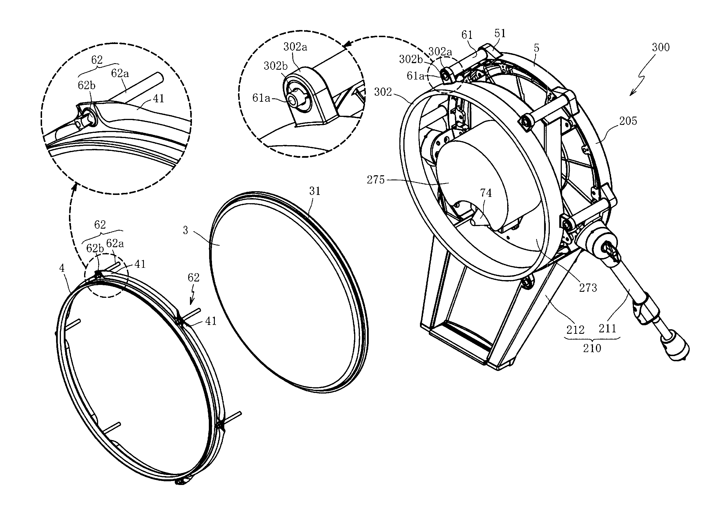
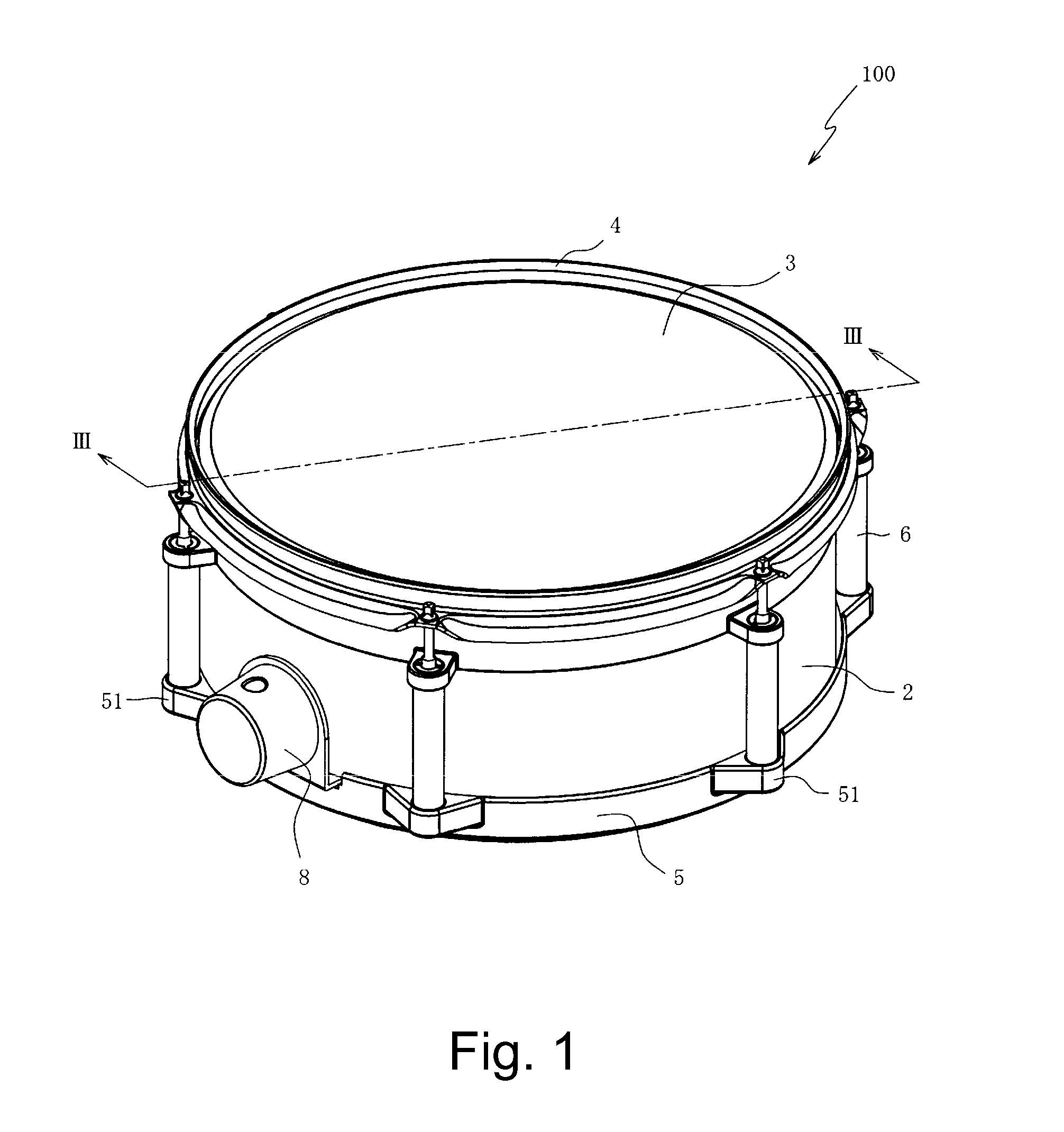
[0036]FIG. 1 is a perspective view of a percussion instrument, such as a tom-tom 100, according to an embodiment of the present invention. The tom-tom 100 may be an electronic percussion instrument played by employing a stick for striking the tom-tom 100. The tom-tom 100 may comprise a shell (or body) 2, a head (or membrane) 3, a first hoop member 4, a second hoop member 5, a plurality of coupling devices 6, and attaching hardware 8. The shell 2 may be a tubular member formed in a cylindrical shape open at both ends. The head 3 may be stretched across a first end of the shell 2 to provide a striking surface. In some embodiments, the head 3 may be made of (but not limited to) a flexible material, such as a soft synthetic resin, an elastomer, rubber, and / or the like. In other embodiments, the head 3 may be made of any suitable material.

[0037]The first hoop member 4 may be arranged along an outer peripheral edge of the head 3 to hold the head 3 against the shell 2. The second hoop memb...


PUM

PropertyMeasurementUnit
rigidityaaaaaaaaaa
weight propertiesaaaaaaaaaa
weightaaaaaaaaaa

Abstract

A percussion instrument may include a plurality of coupling device for operatively connecting a first hoop member, which may be configured to hold down a head arranged across a first end of a shell, with a second hoop member, which may be arranged on a second end of the shell. A sensor adjacent the head configured to detect vibration of the head may be operatively connected to the second hoop member.

Description

CROSS-REFERENCE TO RELATED PATENT APPLICATIONS[0001]Japan Priority Application 2009-137730, filed Jun. 8, 2009 including the specification, drawings, claims and abstract, is incorporated herein by reference in its entirety.BACKGROUND[0002]1. Field of the Invention[0003]Embodiments of the present invention generally relate to an electronic percussion instrument, and, in specific embodiments, to electronic percussion instrument having improved rigidity and / or weight properties.[0004]2. Related Art[0005]Various kinds of electronics drum exist today. Among these, are so-called electronic drums that simulate acoustic drums. Such a drum is furnished with a sensor for detecting a vibration caused from striking the drum. The sound source is controlled based on the detection signal of the sensor and a musical tone is generated based on the striking of the drum.[0006]Japanese Laid-Open Patent Application Publication (Kokai) Number 2008-186036 discloses a drum having a head (striking surface h...

Claims


Application Information

Patent Timeline
Patent Type & Authority Applications(United States)
IPC IPC(8): G10H3/12G10D13/02H04R31/00
CPCG10D13/023G10D13/024Y10T29/49574G10H2230/275G10D13/028G10H3/146G10D13/26G10D13/02G10D13/22G10D13/16G10H2230/301
Inventor MORI, YOSHIAKI
Owner ROLAND CORP
Why Eureka
Try Eureka