A new type of high-precision cloth cutting machine that prevents cloth from moving

A cloth cutting machine and cloth technology, applied in the direction of thin material processing, winding strips, sending objects, etc., can solve the problems of unusable, melting, high temperature of chemical fiber cloth, etc., to ensure normal use and prevent high temperature from sticking to each other Effect

Active Publication Date: 2019-05-24
江苏优恩服饰辅料有限公司
View PDF5 Cites 0 Cited by
  • Summary
  • Abstract
  • Description
  • Claims
  • Application Information

AI Technical Summary

Problems solved by technology

[0004] The purpose of the present invention is to provide a new high-precision cloth cutting machine that prevents cloth from moving, to solve the problem that the cutting accuracy of the current cloth cutting machine proposed in the above-mentioned background technology is not high, and after the cutting blade speed of the cloth cutting machine is increased, The friction between the cutting blade and the cloth is accelerated, which causes some chemical fiber cloth to generate high temperature and melt, resulting in the problem that the cut cloth strips stick to each other and cannot be used

Method used


Image

  • A new type of high-precision cloth cutting machine that prevents cloth from moving
  • A new type of high-precision cloth cutting machine that prevents cloth from moving
  • A new type of high-precision cloth cutting machine that prevents cloth from moving

Examples


Embodiment Construction

[0017] The following will clearly and completely describe the technical solutions in the embodiments of the present invention with reference to the accompanying drawings in the embodiments of the present invention. Obviously, the described embodiments are only some, not all, embodiments of the present invention. Based on the embodiments of the present invention, all other embodiments obtained by persons of ordinary skill in the art without making creative efforts belong to the protection scope of the present invention.

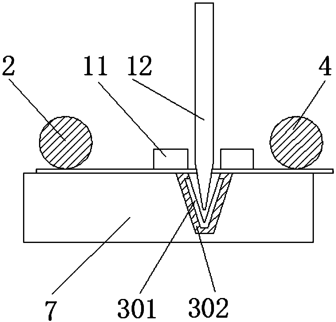
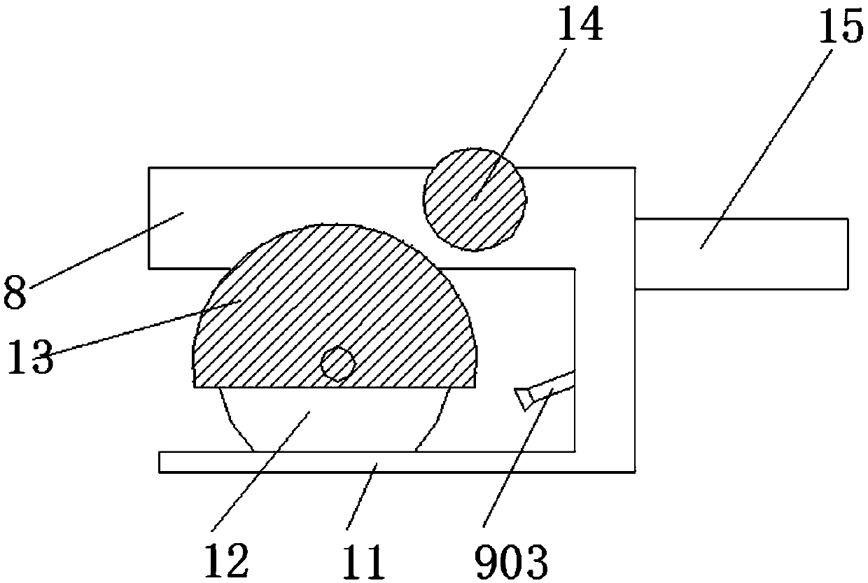
[0018] see Figure 1-4 , the present invention provides a technical solution: a new high-precision cloth cutting machine that prevents cloth from moving, including a feed conveyor belt 1, a front pressure roller 2, a cutting slide rail 3, a limit baffle 5, a discharge conveyor belt 6, Frame 8, spray device 9, cutting blade 12, insulating balance iron 14, control switch 15 and motor 16, feeding conveyor belt 1 is connected with cutting platform 7, and front pre...


PUM


Abstract

The invention discloses a novel high-precision cloth cutting machine for preventing cloth from moving. The novel high-precision cloth cutting machine comprises a feeding conveying belt, a front pressurizing roller, a cutting sliding rail, limiting blocking plates, a discharging conveying belt, a rack, a spray device, a cutting cutter blade, insulation balance iron, a control switch and an electromotor. The cutting sliding rail is arranged on the upper surface of a cutting platform and located between the front pressurizing roller and a back pressurizing roller. The limiting blocking plates are located on the two sides of the cutting platform. The insulation balance iron is located on the left side of the rack. The control switch is located at the tail end of the rack. The electromotor is located on the right side of the rack and connected with the cutting cutter blade. According to the novel high-precision cloth cutting machine for preventing the cloth from moving, the cutting sliding rail is arranged, the cutting sliding rail comprises a cutter grinding device and a sliding rail groove, arranging of the cutter grinding device can grind the cutting cutter blade while the cutting cutter cuts the cloth, and the fact that a cutter edge is blunt, and the cloth can not be effectively and fast cut due to the fact that the cutting cutter blade is not ground for a long time is prevented.

Description

technical field [0001] The invention relates to the technical field of textile machinery, in particular to a new high-precision cloth cutting machine for preventing cloth from moving. Background technique [0002] Various mechanical equipment required to process natural fibers or chemical fibers into textiles. Textile machinery in a broad sense also includes chemical machinery for the production of chemical fibers, and cloth cutting machines are one of the textile machinery. [0003] The cutting accuracy of the current cloth cutting machine is not high, and after the cutting blade speed of the cloth cutting machine is increased, the friction between the cutting blade and the cloth is accelerated, which makes some chemical fiber cloth generate high temperature and melt, causing the cut cloth strips to stick to each other. Unusable, in view of the defects in the above prior art, it is necessary to further improve it to make it more practical, so as to meet the actual use cond...

Claims


Application Information

Patent Timeline
Patent Type & Authority Patents(China)
IPC IPC(8): B65H35/00B65H35/08B65H23/26B65H23/032
CPCB65H23/0324B65H23/26B65H35/0073B65H35/0086B65H35/08B65H2404/15B65H2601/272B65H2601/273B65H2701/174
Inventor 徐强
Owner 江苏优恩服饰辅料有限公司
Why Eureka
Try Eureka