Scintillator plate and radiation detection panel

a technology of radiation detection panel and scintillator plate, which is applied in the direction of optical radiation measurement, fluorescence/phosphorescence, instruments, etc., can solve the problems of reducing sharpness, not reaching the image quality level of screen-film system, and not allowing free image processing or instantaneous transmission, etc., to achieve high optical transmittance, maintain sharpness, and reduce the loss of emitted light

Active Publication Date: 2014-03-06
KONICA MINOLTA INC
View PDF5 Cites 15 Cited by
  • Summary
  • Abstract
  • Description
  • Claims
  • Application Information

AI Technical Summary

Benefits of technology

[0019]The present invention can provide a scintillator plate and a radiation detection panel which demonstrate high optical transmittance of the base of the phosphor columnar crystals constituting the phosphor layer while maintaining the sharpness required for image quality—that is, more emitted light reaches the undercoat layer (preferably, a metal reflective layer)—so that the loss of emitted light is reduced, resulting in excellent light emission luminance.

Problems solved by technology

However, this image information is so-called analog image information and does not allow free image processing or instantaneous transmission such as that of digital image information, which continues to develop in recent years.
However, due to insufficient sharpness and spatial resolution, this technology has not reached the image quality level of screen-film systems.
However, as the thickness of the phosphor layer increases, the scattering of emitted light occurs within the phosphor layer, and the sharpness is diminished.
Even if the reflectance of the reflective layer is improved as in Patent Document 1, the optical transmittance at the base of the columnar crystals is low (Patent Document 2), and the original performance cannot be derived.
Therefore, the improvement in the light emission luminance cannot be considered sufficient, and although there is technology which improves the base of the columnar crystals (Patent Document 3), there remains room for improvement.

Method used


Image

  • Scintillator plate and radiation detection panel
  • Scintillator plate and radiation detection panel
  • Scintillator plate and radiation detection panel

Examples


working example 1

Step of Forming an Undercoat Layer on a Substrate

Dry Process

[0213]A “UPILEX-125S” polyimide film (thickness: 125 μm) produced by Ube Industries, Ltd. was placed in the CVD device of FIG. 3 as a substrate, and an undercoat layer comprising parylene C having a melting point of 290° C. (produced by Parylene Japan Co., Ltd.) was formed on one side thereof. The thickness of the undercoat layer was 3 μm. The substrate and the undercoat layer are then formed integrally to serve as a support.

[0214]Parylene C has a basic structure in which a benzene ring is polymerized via —CH2—, and one hydrogen atom of this benzene ring is substituted with chlorine.

Vapor Deposition Step

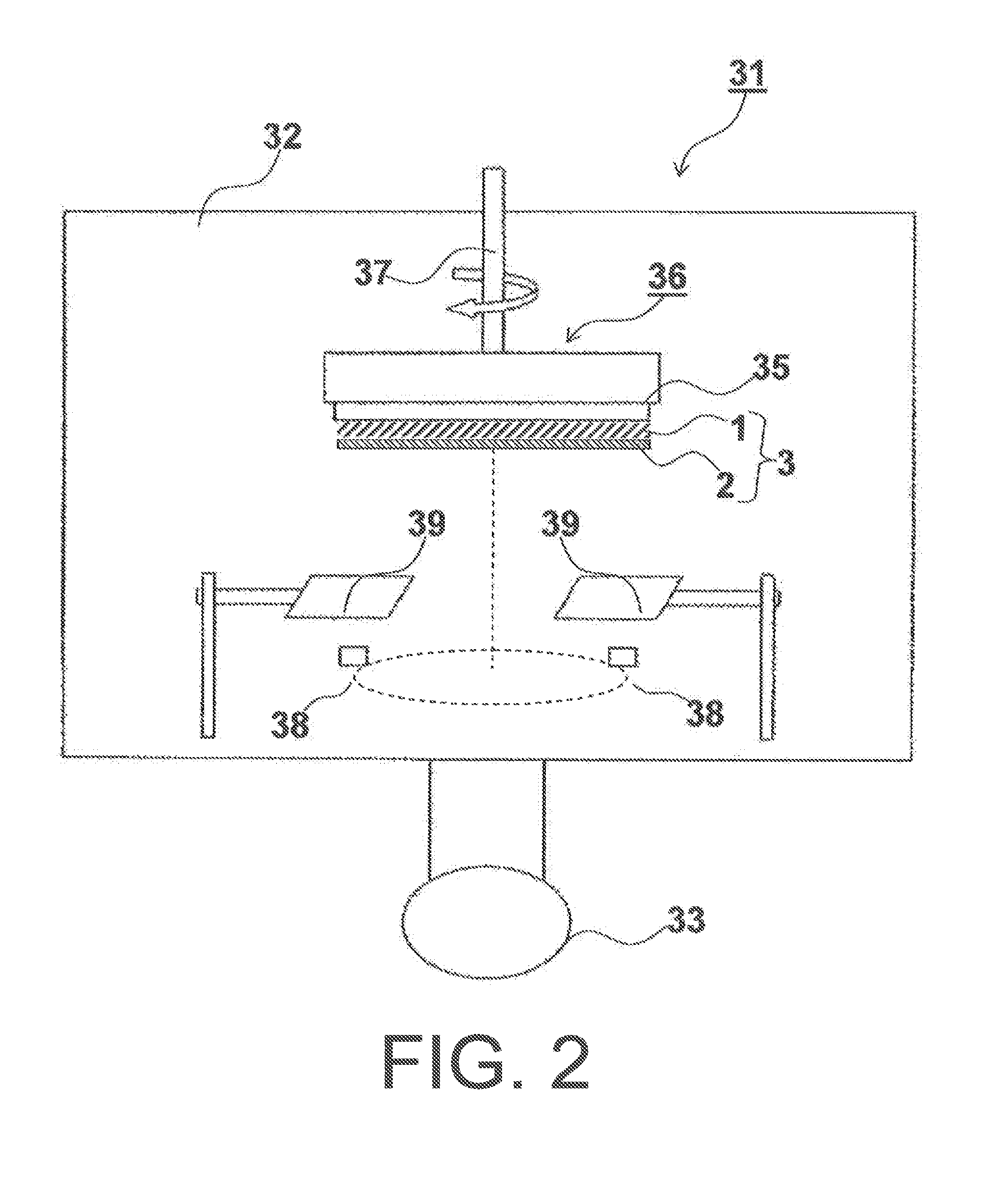
[0215]This is described with reference to FIG. 2.

[0216]First, two resistance heating crucibles were respectively filled with cesium iodide (CsI) serving as a phosphor parent compound and an activator (TlI), and these were used as evaporation sources (38). The support (3) was placed in a metal frame (not illustrated) of the s...

working example 2

[0235]A scintillator plate was produced in the same manner as in Working Example 1 with the exception of changing the vacuum from 0.05 Pa to 0.1 Pa in Working Example 1.

working example 3

[0236]A scintillator plate was produced in the same manner as in Working Example 1 with the exception of changing the step of forming the undercoat layer on the substrate as follows in Working Example 1.

Step of Forming an Undercoat Layer on a Substrate—Wet Process—

[0237]Silver was sputtered onto a polyimide film with a thickness of 125 μm (“UPILEX-125S” produced by Ube Industries, Ltd.) as a substrate so that the film thickness was 1,000 Å (=100 nm).

[0238]A Vylon (registered trademark) “200 (brand)” (produced by Toyobo Co., Ltd.) with a glass transition point of 67° C. was dissolved in methyl ethyl ketone (MEK) and applied so as that a dry film thickness was 3 μm, to form an undercoat layer.


PUM


Abstract

Problem: The object of the present invention is to provide a scintillator plate and a radiation detection panel demonstrating excellent light emission luminance while being limited to a thickness which maintains the sharpness required for image quality.Solution: A scintillator plate comprising an undercoat layer and a phosphor layer, wherein the phosphor layer comprises phosphor columnar crystals using the undercoat layer side as a base, and wherein when the phosphor layer is halved in terms of thickness in the lamination direction and the respective halves constitute a tip side portion and a base side portion of the phosphor columnar crystals, a ratio (B / A) of an optical transmittance (B) of the base side portion to an optical transmittance (A) of the tip side portion is not less than 70% and not more than 99%.

Description

TECHNICAL FIELD[0001]The present invention relates to a scintillator plate that can be used in an indirect conversion type flat panel detector (FPD), a radiation detection panel consisting of the scintillator plate, and a manufacturing method thereof.BACKGROUND ART[0002]Conventionally, radiographic imaging such as X-ray imaging has been widely used for the diagnosis of symptoms in healthcare settings. In particular, as a result of improvements in sensitivity and image quality achieved over its long history, radiographic imaging using an intensifying screen-film system is now used in healthcare settings throughout the world as an imaging system combining high reliability and excellent cost performance. However, this image information is so-called analog image information and does not allow free image processing or instantaneous transmission such as that of digital image information, which continues to develop in recent years.[0003]Radiographic image detectors for detecting digitally ...

Claims


Application Information

Patent Timeline
Patent Type & Authority Applications(United States)
IPC IPC(8): G01T1/20
CPCG01T1/2012G01T1/202
Inventor KONDO, MASASHIITAYA, KEIKO
Owner KONICA MINOLTA INC
Why Eureka
Try Eureka