Light scanning probe apparatus using light of low coherence

a light scanning and low coherence technology, applied in the field of optical scanning probe devices, can solve the problems of difficult observation at a given distance from living organ tissue, cumbersome handling, and high cost of laser light sources, and achieve the effect of convenient observation

Inactive Publication Date: 2005-05-03
OLYMPUS CORP
View PDF5 Cites 115 Cited by
  • Summary
  • Abstract
  • Description
  • Claims
  • Application Information

AI Technical Summary

Benefits of technology

[0020]It is an object of the present invention to provide an optical scanning probe device which can perform observation while being positioned at a given distance, or the like, from the living-body tissue which becomes an observation target.
[0021]It is another object of the present invention to provide an optical scanning probe device in which the focus position can be set variably.
[0022]Other objects include that the positional relationship between the observation target and the optical probe is retained stably and, therefore, operational ease is improved, that the positional relationship between the forceps hole of the endoscope, in which an optical probe is inserted, and the positioning member is adjusted and, therefore, the probe can exhibit intrinsic optical performances, that the light beam is made to enter nearly perpendicularly into the observation target, the optical probe is precisely positioned in order to locate the focus of the light beam at a proper position in accordance with the observation purpose and, therefore, tomogram information with precise information regarding distance can be gained in accordance with the observation purpose, that biopsy is simultaneously performed with ease from the light scanning position at the same time as the tomography observation with the optical probe, that when an endoscope having one forceps channel is used, even if observation and biopsy with the optical probe cannot be performed simultaneously, marking is performed at the part observed and, therefore, biopsy is performed later using this as a landmark, that adjustment of the amount of protrusion of the probe for positioning can be performed with ease, that movement of the optical probe in the direction perpendicular to the longitudinal axis is inhibited and, therefore, the pint position of the light beam can be positioned further precisely, and that adjustment of the amount of protrusion of the optical probe for positioning can be performed with ease and, in addition to this, movement of the optical probe in the direction perpendicular to the longitudinal axis is stopped and, therefore, the pint position of the light beam can be positioned further precisely.
[0025]a flexible sheath in which at least the tip side has excellent light transmittance,
[0030]wherein the focus position of the light exiting from the aforementioned light exit-entrance portion can be adjusted in the neighborhood of the aforementioned predetermined distance by the aforementioned positioning member and, therefore, observation is performed with ease.

Problems solved by technology

However, a laser light source, which emits very short-pulsed light on the order of picosecond pulse, is expensive and is large, and cumbersome handling is required.
However, as is shown in FIG. 4, etc., in the publication of Japanese Unexamined Patent Application Publication No. 11-56786, since the optical scanning probe device of the prior example is nearly in the shape of a cylinder, it is difficult, for example, to observe at a given distance from the living-organic tissue.
However, it is difficult to observe while the outer surface of the sheath is held at a position some distance from the living-body tissue surface larger than that in the aforementioned condition.
Consequently, many specifically designed optical scanning probe devices have been required and therefore, a large burden has been born by the user.
Furthermore, the management thereof has been cumbersome.
However, regarding an optical probe device of a conventional example which has been inserted through an endoscope as shown in FIG. 4, etc., in the publication of Japanese Unexamined Patent Application Publication No. 11-56768, it has been very difficult to perform stable positioning while fine adjustment among the observation target, light beam focus, entry angle, etc., has been made by endoscope operation in accordance with the observation purpose in the state in which the optical probe device is protruded from the endoscope tip.
In addition, it has been attended with significant difficulties to perform biopsy aiming at the scanning position of the light beam by the combination of the endoscope having two forceps channels and the biopsy forceps.

Method used


Image

  • Light scanning probe apparatus using light of low coherence
  • Light scanning probe apparatus using light of low coherence
  • Light scanning probe apparatus using light of low coherence

Examples


first embodiment

[0145](First Embodiment)

[0146]The first embodiment according to the present invention will be described with reference to FIG. 1 to FIG. 9.

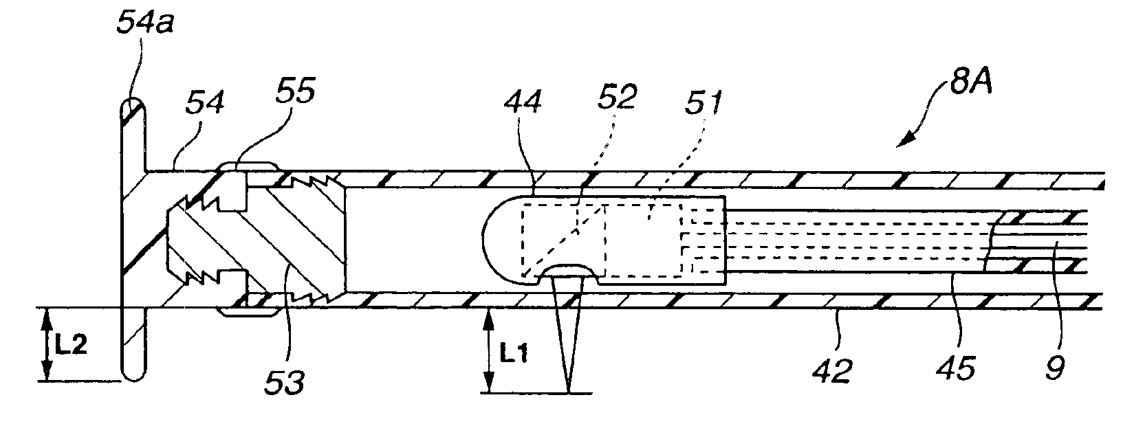
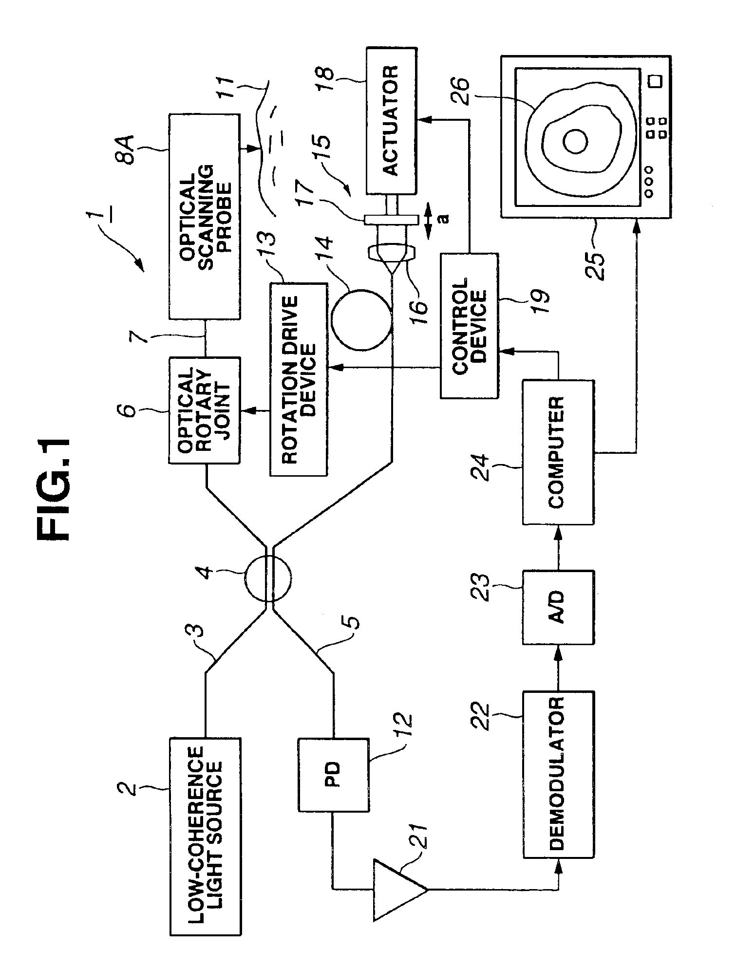
[0147]An optical tomography device 1 shown in FIG. 1 includes a low-coherence light source 2, for example, a super luminescent diode (hereafter abbreviated as SLD). This low-coherence light source 2 is provided with characteristics of low-coherence light exhibiting coherence only in a short-distance range in which the wavelength thereof is, for example, 1,300 nm and the coherence length is, for example, on the order of 17 μm. That is, in the case where this light is divided into, for example, two portions and, thereafter, the two portions are mixed again, when the difference between two optical path lengths from the division point to the mixing point is within the short-distance range on the order of 17 μm, this light is detected as the light in which interference has occurred, and when the optical path length is larger than that, characteristics...

second embodiment

[0203](Second Embodiment)

[0204]The second embodiment according to the present invention will be described with reference to FIG. 10 and FIG. 11.

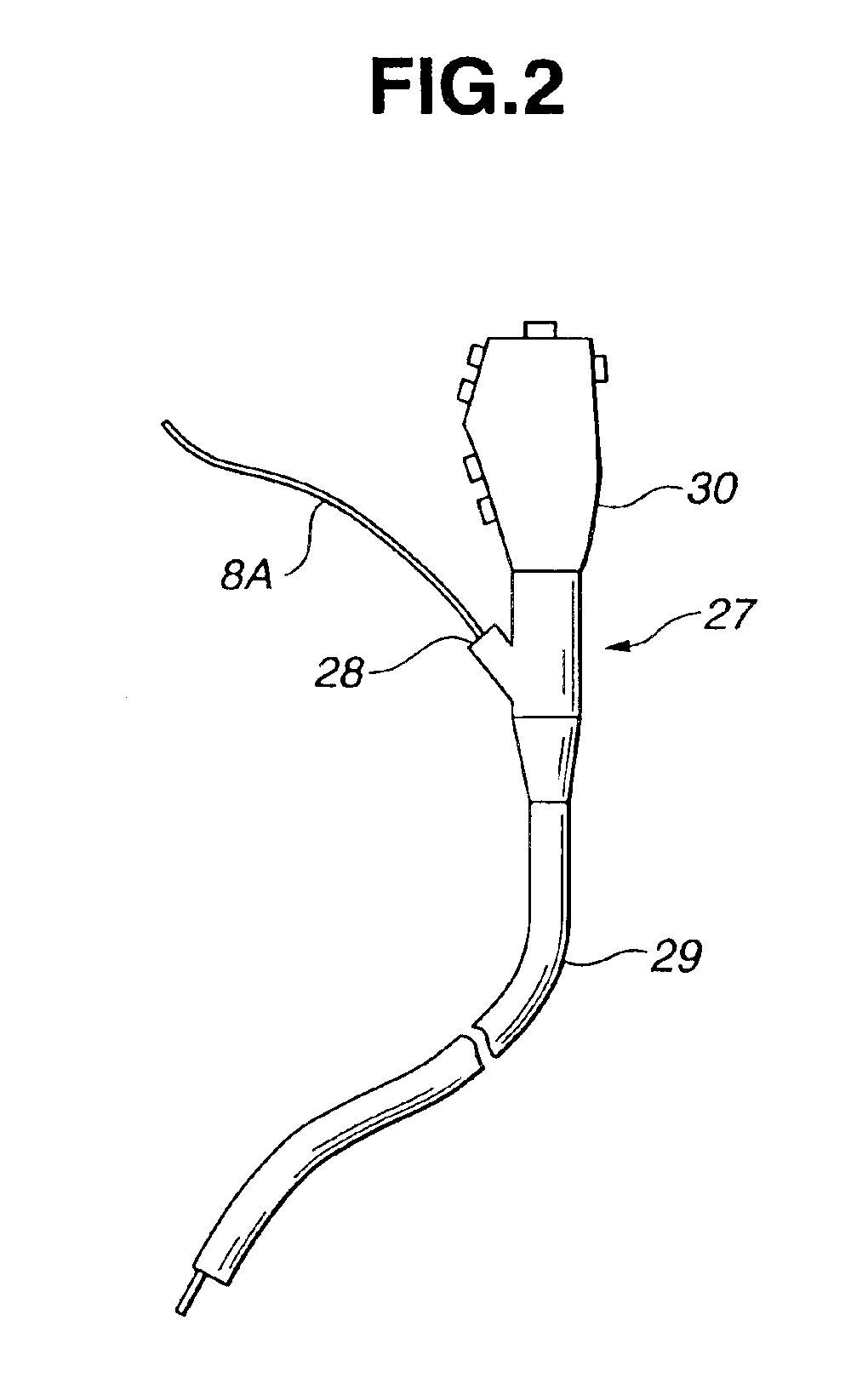
[0205]An optical probe 8C according to the present embodiment includes an optical probe main body 58 as shown in FIG. 11 and a sheath portion with blade 59A freely attachable to and detachable from the optical probe main body 58.

[0206]This optical probe 8C has the structure of the optical probe 8A according to the first embodiment, wherein an inner sheath 60 which covers the flexible shaft 45, housing 44, etc., and which has pliability and light transmittance is provided inside the sheath 42, and at the base end of the inner sheath 60, a connection portion 61 is provided in order that the base end of the sheath 42 can be freely attached thereto and detached therefrom. The tip of the inner sheath 60 is blocked watertight by, for example, a half-round tip cap 62.

[0207]An internal thread portion (constituting the connection portion 61) is provi...

third embodiment

[0213](Third Embodiment)

[0214]The third embodiment according to the present invention will be described with reference to FIG. 12 and FIG. 13.

[0215]Regarding an optical probe 8D according to the present embodiment, in the first embodiment, the connection member 53 is fixed watertight to the tip of the sheath 42 on this connection member 53, an external thread portion 64 is provided in order that the blade member 54 side provided with the blade 54a can be freely attached and detached so as to form an optical probe main body 65, and blade unit 67A provided with a internal thread member 66, which can be freely attached to and detached from the external thread portion 64 by thread engagement, is formed on the blade member 54 side.

[0216]In the present embodiment, the blade 54a is formed at the rear end portion of the blade member 54. In the present embodiment, a protrusion portion (or small diameter portion) 68, which is protruded from the outer diameter of the internal thread member 66 ...


PUM

PropertyMeasurementUnit
coherence lengthaaaaaaaaaa
distanceaaaaaaaaaa

Abstract

A flexible shaft driven to rotate is inserted through a transparent sheath having pliability. By a fiber inserted through the inside thereof, low-coherence light is guided and is made to exit to a living-body tissue side which is an observation target through a lens and a prism forming an exit and entrance portion at the tip portion. Subsequently, the light reflected on the living-body tissue side is guided in order to produce an image. In that case, a positioning member for keeping the exit and entrance portion and the living-body tissue at a proper distance is formed at the tip portion of the sheath or the tip portion of an endoscope through which an optical probe is inserted and, therefore, a stable tomogram image can be produced.

Description

CROSS REFERENCE TO RELATED APPLICATION[0001]This application is a divisional of U.S. application Ser. No. 10 / 091,626 filed Mar. 6, 2002 now U.S. Pat. No. 6,797,931 entitled LIGHT SCANNING PROBE APPARATUS USING LIGHT OF LOW COHERENCE, which claims the benefit of Japanese Application Nos. 2000-186664 filed on Jun. 21, 2000 and 2001-069107 filed on Mar. 12, 2001, the contents of which are incorporated by this reference.BACKGROUND OF THE INVENTION[0002]1. Field of the Invention[0003]The present invention relates to an optical scanning probe device in which low-coherence light is guided and is made to exit to living-body tissue, and reflected light therefrom is guided so as to produce an optical tomogram.[0004]2. Description of Related Art[0005]In recent years, in the case where living-body tissue is diagnosed, in addition to an imaging device to gain optical information regarding the surface condition of the tissue, an optical CT device which can gain optical information regarding the i...

Claims


Application Information

Patent Timeline
Patent Type & Authority Patents(United States)
IPC IPC(8): G02B23/24A61B1/00G01B11/00A61B10/00G01N21/17H04N7/18
CPCA61B1/00087A61B1/00089A61B1/00096A61B1/00101A61B1/00172G02B23/2407A61B1/042A61B5/0062A61B5/0066A61B5/6852B82Y15/00A61B1/018
Inventor IIZUKA, SHUHEIHORII, AKIHIROISHIHARA, YASUSHIGEMATSUI, RAIFUKANEKO, MAMORU
Owner OLYMPUS CORP
Why Eureka
Try Eureka