Two-port tire valve stem

Active Publication Date: 2012-04-03
HAWKSHEAD SYST
View PDF8 Cites 19 Cited by
  • Summary
  • Abstract
  • Description
  • Claims
  • Application Information

AI Technical Summary

Benefits of technology

[0010]Presented herein is a two-port valve stem of substantially rigid construction that, when fitted with valves and attached to a wheel rim, permits the adjustment of air pressure via one of the ports while a pressure sensor remains mounted on the other port.

Problems solved by technology

Also, the rubber valve stem may become brittle or deteriorate due to exposure to the sun and contact with various salts, oils and other road-related substances.
Under-inflated tires may result in rapid and excessive wear on the outer portions of the tread as well as improper vehicle handling.
On the other hand, over-inflated tires may result in rapid and excessive wear on the middle part of the tread, and may possibly lead to a blowout.
Firstly, this method is complicated and requires an additional tool, which may be unavailable when needed and must be purchased at an additional cost to the operator.
Secondly, the operation is time consuming for the operator as he must remove the valve cap for each tire, apply the pressure gauge, and then re-fasten all the valve caps.
However, when inflation or deflation of the tire is required, the tire pressure sensor has to be removed, which is still inconvenient and time consuming.
Furthermore, it may be more time consuming because such pressure sensors are often fitted with a locking mechanism that needs to be undone and re-done.
Such sensors, when detached while adjusting the tire pressure, may be lost in the same way that valves caps are often lost or forgotten.
This is more of a problem due to the greater expense of the pressure sensors.
However, as the disclosed valves and pressure detectors are not an integral part of the tire valve, the whole assembly becomes cumbersome and too weighty, affecting a wheel's balance.
If the adapter and sensor are attached to a rubber valve stem, centripetal forces due to wheel rotation cause the rubber stem to deform while driving, which may lead to damage of the stem, deflation of the tire and a possible accident.
A further problem with the use of an adaptor is that its use introduces at least one more joint through which air or contaminants may leak.
Other limitations of the prior art will become apparent upon reading the specification and study of the drawings.

Method used


Image

  • Two-port tire valve stem
  • Two-port tire valve stem
  • Two-port tire valve stem

Examples


Embodiment Construction

[0020]The drawings and the following description depict specific embodiments to teach those skilled in the art how to make and use the best mode of the invention. However, those skilled in the art would appreciate that the features described below may be combined in various ways to form multiple variations of the invention.

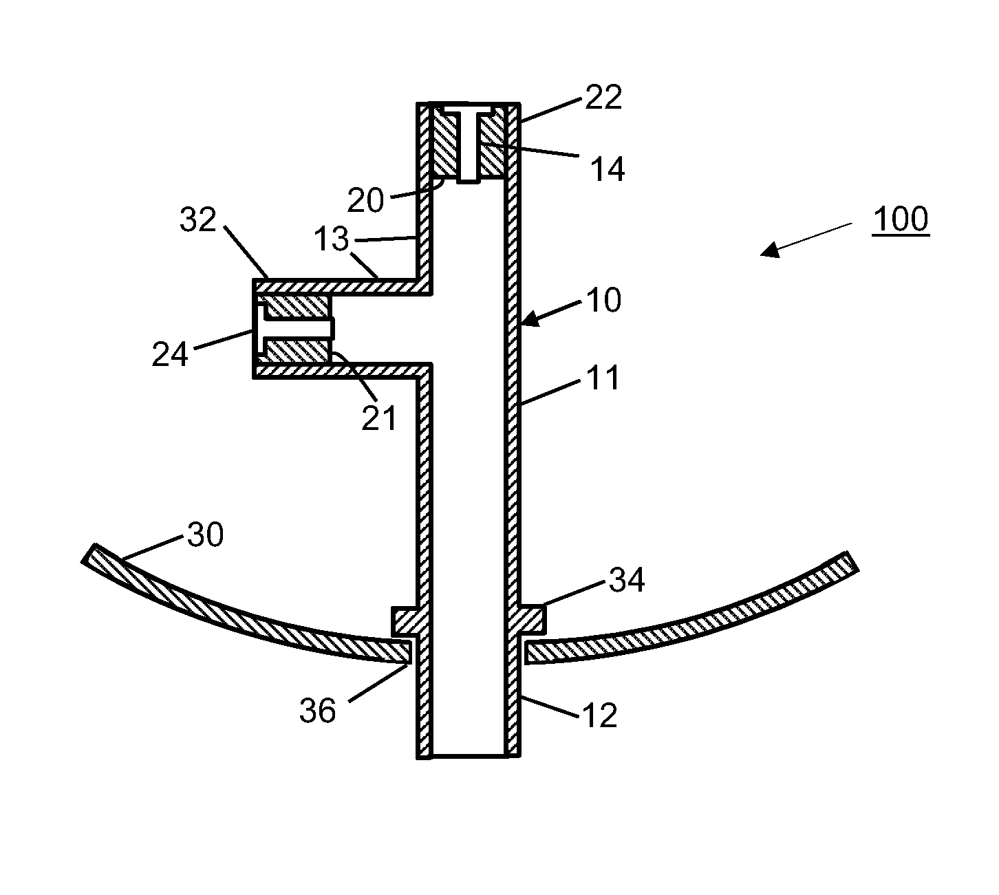
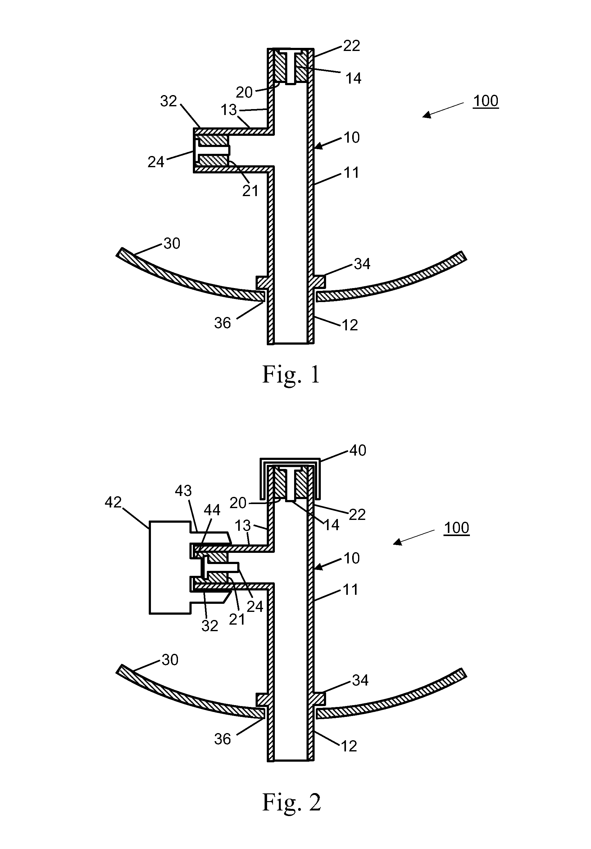
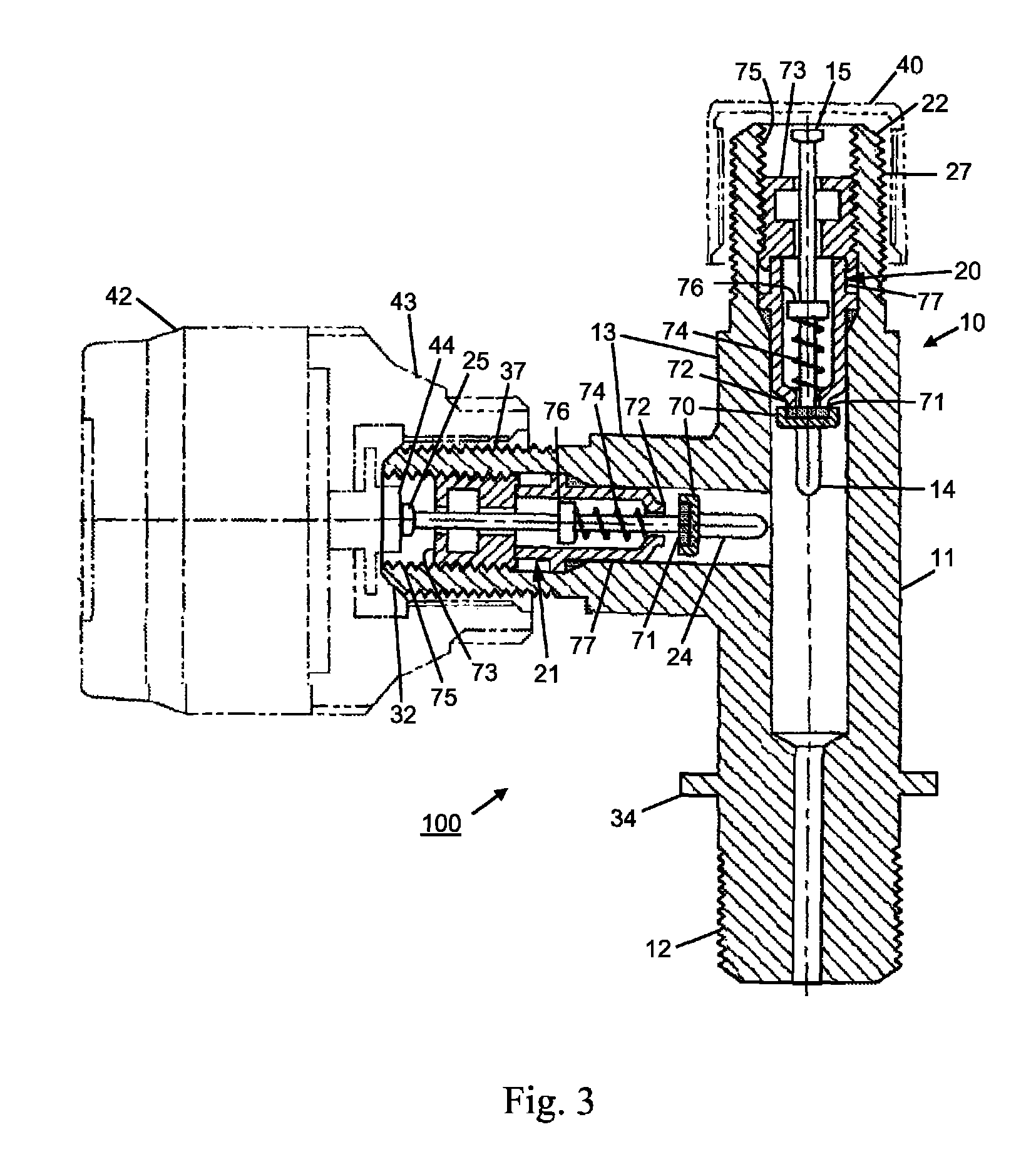
[0021]Referring to FIG. 1, there is schematically illustrated a two-port tire valve assembly, generally designated 100, incorporating a two-port valve stem 10 according to an exemplary embodiment of the present invention. The two-port valve stem 10 has an elongated body 11 of hollow configuration. The hollow body 11 has a first end portion 12 and a second end portion 13. The first end portion 12 is configured to be secured within an aperture 36 of a wheel rim 30. The wheel rim 30 is used to support a vehicle tire (not shown). The second end portion 13 has a first port 22 and a second port 32 arranged in a branched configuration. The ports 22 and 32 are integral pa...


PUM


Abstract

A two-port tire valve stem has a body, preferably of substantially rigid construction, with a first end portion adapted to be mounted to a wheel rim and a second end portion with at least two ports in a branched configuration, each supporting a valve. One of the valve ports may be used for inflation or deflation concurrently with the other being coupled to a pressure sensor for monitoring the air pressure in the tire. The two-port tire valve stem is adapted to be rigidly mounted to an outer of a pair of adjacent wheels, using a bracket, while its first end is adapted to be connected in fluid communication with the inner of the pair of wheels.

Description

TECHNICAL FIELD[0001]The present invention relates to a tire valve, and more particularly, the present invention relates to a two-port tire valve stem having an inflation valve port and a separate valve port onto which a pressure sensor may be mounted.BACKGROUND OF THE INVENTION[0002]A tire valve usually has a valve stem with a valve that extends through a stem hole in a wheel rim. The inner volume of the valve stem is in fluid communication with the hollow chamber enclosed by the tire. The valve in the stem permits air to be introduced into the tire and prevents escape of the air from the tire through the valve stem. The valve stem may be rubber or a rigid, metal stem, and is usually provided with a removable valve cap or dust cap on its threaded end. The cap is used to protect the inside of the valve.[0003]Even though a rubber valve stem may be resilient, so that it may be sealed in the wheel rim opening as the stem is pulled into place, the rubber is exposed to various sharp obje...

Claims


Application Information

Patent Timeline
IPC IPC(8): B60C23/02
CPCB60C23/0496B60C29/06
Inventor GRACE, JULIAN
Owner HAWKSHEAD SYST
Why Eureka
Try Eureka