Base structure for monitor

a technology for monitors and bases, applied in the field of monitor bases, can solve the problems of wasting monitors' stand space, abandoning the original base structure, and wasting money, and achieve the effect of saving a significant amount of resources, reducing waste of money and disassembly and installation time, and reducing the waste of tim

Inactive Publication Date: 2012-04-03
TPV ELECTRONICS (FUJIAN) CO LTD
View PDF20 Cites 13 Cited by
  • Summary
  • Abstract
  • Description
  • Claims
  • Application Information

AI Technical Summary

Benefits of technology

[0005]The primary object of the present invention is to incorporate the supporting base structure and the suspending stand, so as to reduce the waste of money and disassembling and installing time and to save a significant amount of resources.
[0008]In the aforementioned base structure, said slide portion further contains a thumb screw in order to fasten said slide portion and stop said slide portion from moving. Said thumb screw is matched to an external thread of said slide portion by an internal thread so that the friction between said thumb screw and said rear casing may increase or decrease by fastening or loosening said thumb screw.
[0015]Therefore, the base structure for a monitor can improve the inconvenience of the prior art by incorporating the supporting base structure and the suspending stand. Thus, there is no need to additionally purchase a suspending stand, and resources as well as time of disassembling the conventional base and installing the purchased stand will be saved. Therefore, the present invention may have tremendous potential in the market.

Problems solved by technology

Therefore, additional purchase of a suspending stand for the monitor and abandonment of the original base structure are absolutely required and inevitable.
However, it's money-consuming.
Moreover, the disassembly of the original base structure and the installation of the purchased suspending stand are time-consuming, resulting in so much inconvenience.
Thus, preventing its inconvenience, incorporating the supporting base structure and the suspending stand into a single monitor, reducing waste of money and disassembling and installing time, and saving a significant amount of resources are virtually a critical issue to be dealt with.

Method used


Image

  • Base structure for monitor
  • Base structure for monitor
  • Base structure for monitor

Examples


Embodiment Construction

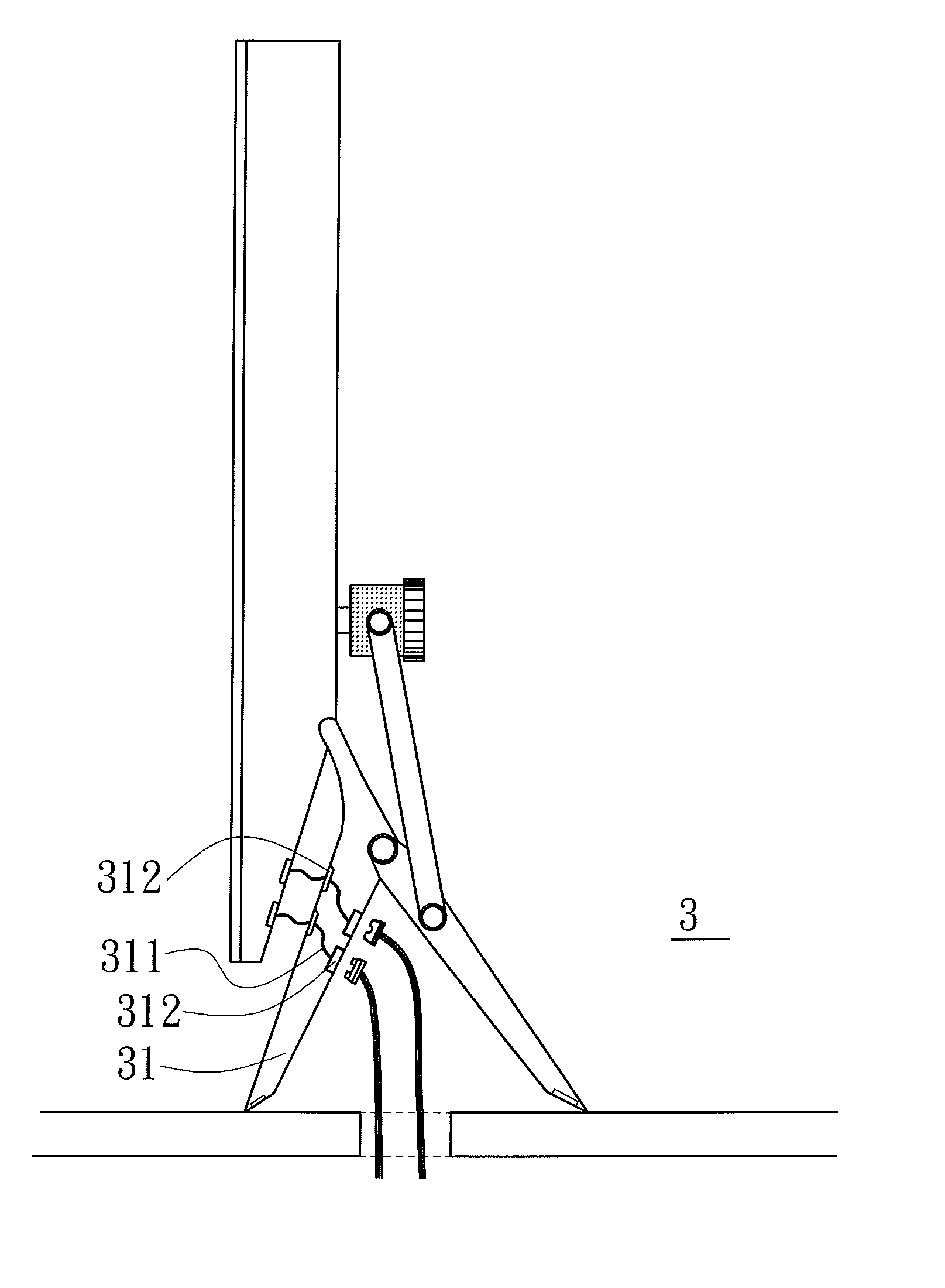
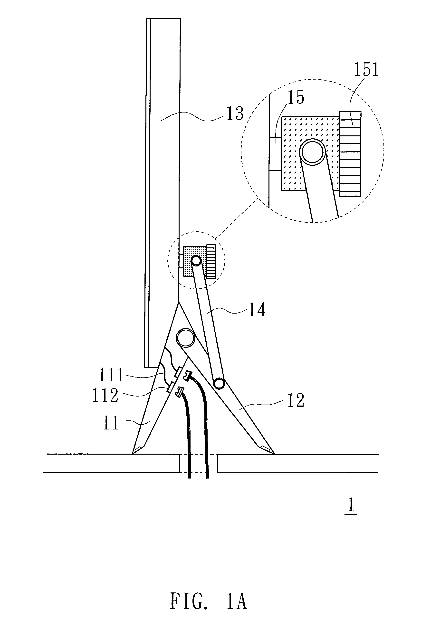
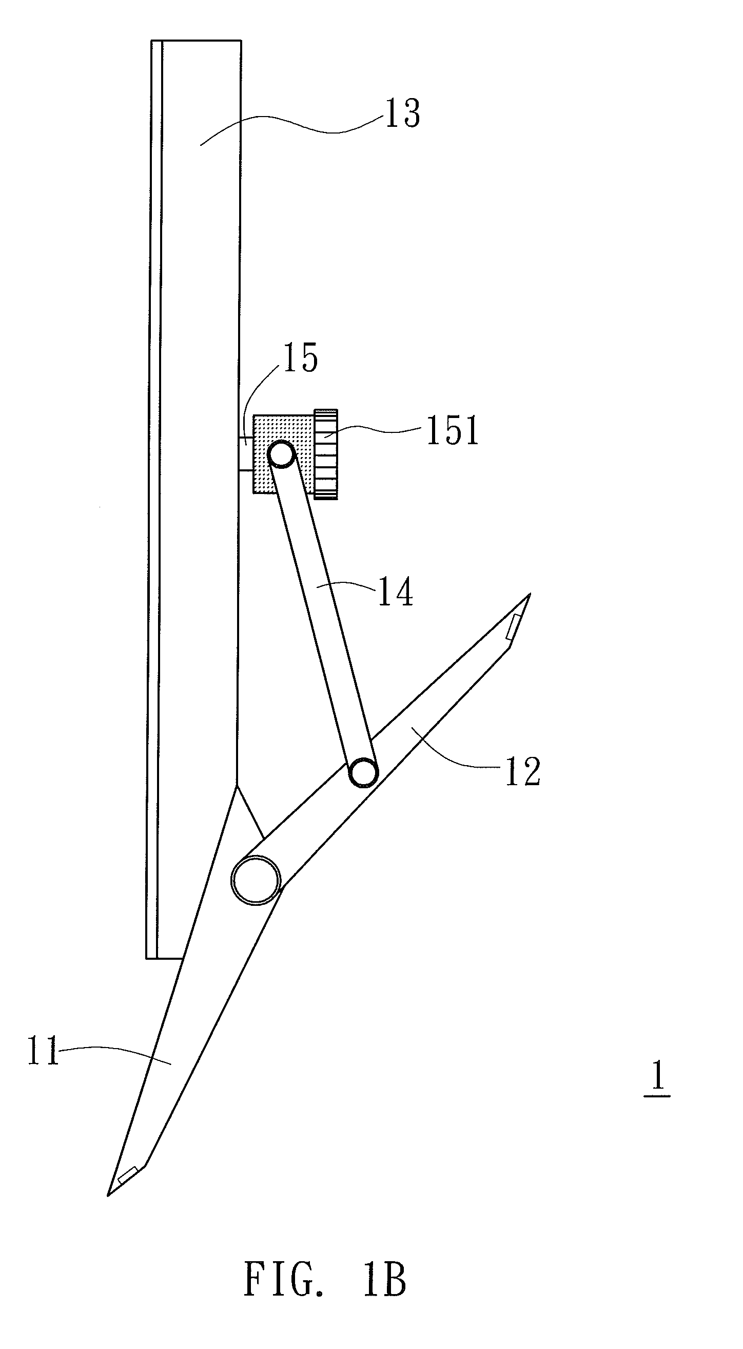
[0025]FIG. 1A is a diagram of a monitor with a base structure when the monitor is placed on the desk. As shown in FIG. 1A, the monitor 1 is placed on the desk, and the rear casing 13 includes a push bar 14, a first stand 11, a second stand 12, a slide portion 15 and a thumb screw 151. The slide portion 15 can be repeatedly moved up and down on the rear casing 13. The top end of the push bar 14 is pivotally linked to the slide portion 15 and can be repeatedly moved along with the slide portion 15. The first stand 11 is firmly disposed on the rear casing 13. The left end of the second stand 12 is pivotally linked to the first stand 11. The bottom end of the push bar 14 is pivotally linked to the middle of the second stand 12. The first stand 11 contains a plurality of wires 111 inside and further contains a plurality of sockets 112 correspondingly disposed at a rear side of the first stand 11. The sockets 112 are adapted to receive the signal cable or the power cord. In this embodimen...


PUM


Abstract

A base structure can support a monitor. A fixed portion is firmly disposed on the rear casing of the monitor and contains at least one slide rail. A slide portion can move up and down the slide rail. A spring is linked to the fixed portion and the slide portion. One end of the push bar is pivotally linked to the slide portion. A first stand is firmly disposed on the rear casing. A second stand is pivotally linked to the first stand. Another end of the push bar is pivotally linked to the second stand. In this manner, the monitor may adjust the expanding angle of the second stand so as to place the monitor on the desk or hang the monitor on the wall.

Description

FIELD OF THE INVENTION[0001]The present invention relates to a base structure for a monitor and, particularly, to the base structure which can adjust its stand so as to place the monitor on the desk or to hang the monitor on the wall.DESCRIPTION OF THE PRIOR ART[0002]In recent years, due to the lower cost of the flat panel monitor, the monitor has gradually come into vogue in home TV and computer display usages. Besides, because of its thinness and light characteristics comparative to cathode-ray-tube television, the flat panel monitor will be more and more favorable and easily seen in public such as at stations, hospitals, convenient stores or theaters. Flat panel monitors not only can be utilized to deliver messages, but also can achieve some advertising purposes. Thus, the usage and application of flat panel monitors will be wider and wider.[0003]Conventionally, the flat panel monitor has a base structure to support the monitor so as to place the monitor on the desk. However, exc...

Claims


Application Information

Patent Timeline
Patent Type & Authority Patents(United States)
IPC IPC(8): A47F1/10A47F5/00A47F7/00A47F5/12F16M13/00F16M11/00
CPCF16M11/00F16M11/04F16M11/046F16M11/10F16M11/16F16M13/02F16M13/022F16M2200/08Y10S248/918Y10S248/919Y10S248/921Y10S248/922Y10S248/917Y10S248/92Y10S248/923
Inventor WANG, XIAOWANG, LIXIAHUANG, WEN-HSIUNG
Owner TPV ELECTRONICS (FUJIAN) CO LTD
Why Eureka
Try Eureka