Deformable sensor system

a sensor system and deformation technology, applied in the field of deformation sensor systems, can solve the problems of inability to estimate an appropriate pressure distribution, the number of electrodes has become very enormous, and the expansion/contracting property of the sensor per se is impaired, so as to achieve high pressure distribution and reduce the number of electrodes

Inactive Publication Date: 2012-04-03
SUMITOMO RIKO CO LTD +1
View PDF6 Cites 76 Cited by
  • Summary
  • Abstract
  • Description
  • Claims
  • Application Information

AI Technical Summary

Benefits of technology

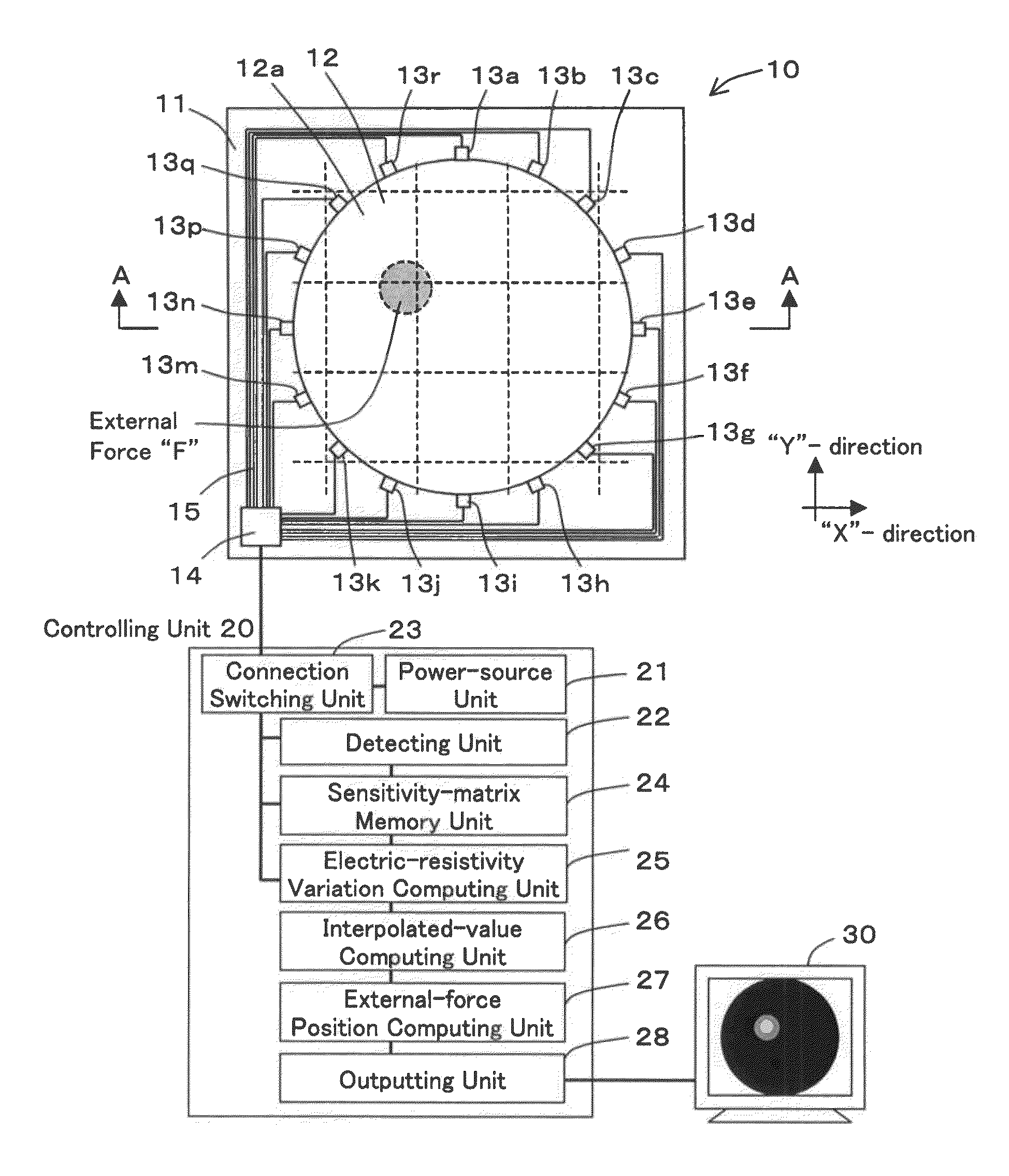
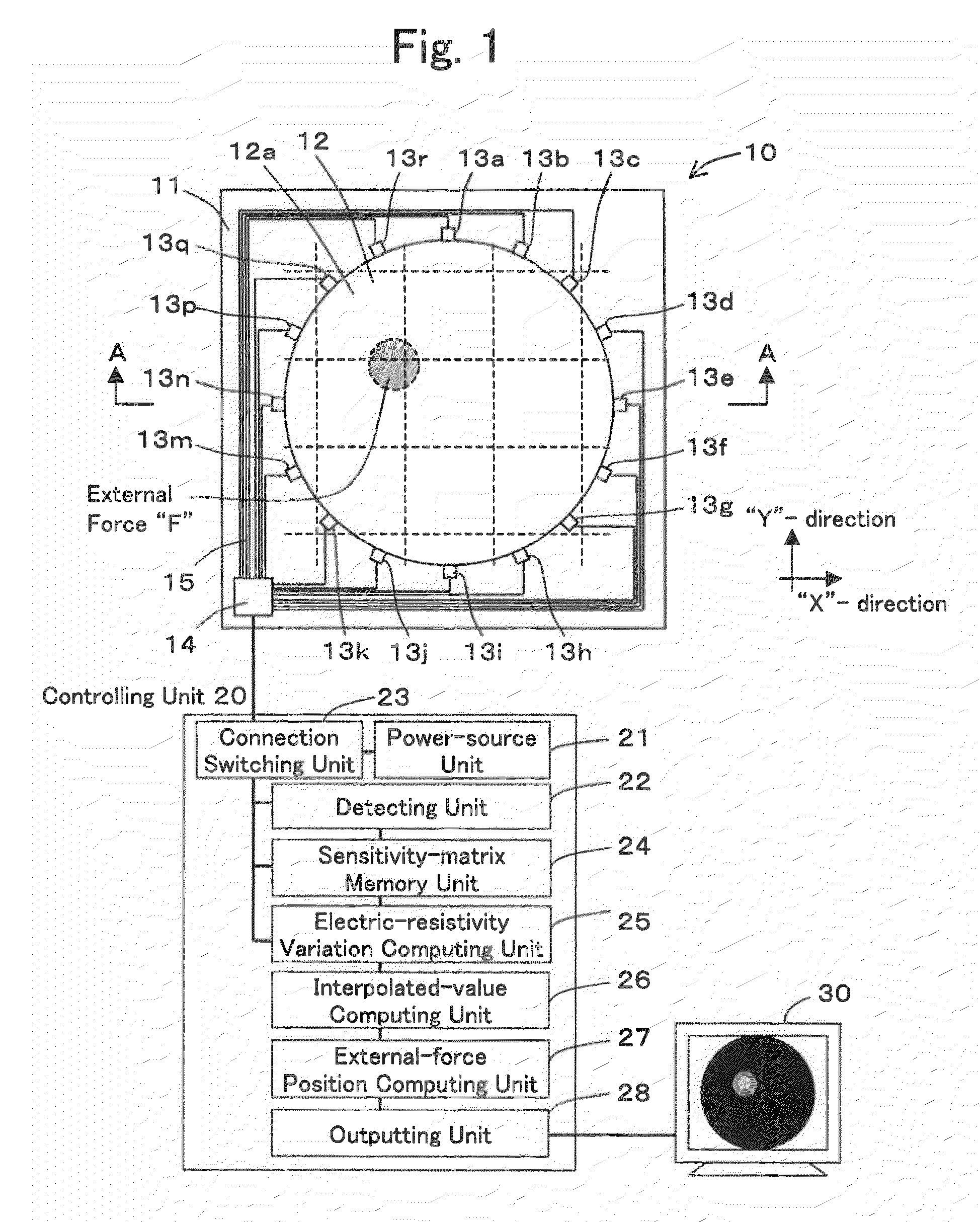
[0011]The present invention has been done in view of such circumstances, and it is an object to provide a deformable sensor system, which makes it possible to obtain a more highly accurate pressure distribution while reducing the number of electrodes.

Problems solved by technology

Thus, since the electrodes are disposed on the entire pressure-receiving surface, the number of the electrodes have become very enormous when enlarging the pressure-receiving surface.
If such is the case, there has been such a problem that, since the wiring becomes enormous, the mountability has become poor and further the expanding / contracting property of sensor per se has been impaired.
However, in the inverse-problem analysis, since there is no uniqueness in solution, it is not possible to estimate an appropriate pressure distribution in the case of obtaining it based on the least-square method that is free of any restrictions.

Method used


Image

  • Deformable sensor system
  • Deformable sensor system
  • Deformable sensor system

Examples


first example

Modified Mode of First Example

[0131]A modified mode of the sensor structure 10, which constitutes the deformable sensor system of the First Example, will be explained with reference to FIG. 10. FIG. 10 is diagram for illustrating the modified mode of the sensor structure 10. Although the deformable sensor 12 was adapted into one that comprises one piece of a circular flat plate alone in the First Example, it is allowable that, as shown in FIG. 10, the deformable sensor 12 can comprise a solid three-dimensionally configured member and can have a plurality of the pressure-receiving surfaces 12a on its faces. In FIG. 10, all of the six faces are adapted into the pressure-receiving surface 12a, respectively. And, the electrodes 13 are disposed in a quantity of a plurality of pieces on the peripheral rim of the respective pressure-receiving surfaces 12a. In this case, it is possible to detect a position in each of the pressure-receiving surfaces 12a, position which receives an external f...


PUM


Abstract

A deformable sensor system that can be used for pressure-distribution sensors. The deformable sensor system makes it possible to obtain a pressure distribution with a much higher accuracy, while reducing the number of electrodes. The system utilizes a deformable sensor which can detect deformation as the electric resistivity of the surface increases monotonically as an elastic deformation variation in each of the elastic deformations increases. Based on a voltage being detected by means of a detecting unit, the deformable sensor electric-resistivity variation computing unit computes the variation of the electric resistivity based on the method of least squares with a restriction condition imposed thereon. The system uses such a technology as “EIT” that is based on an inverse-problem theory. At an external-force position computing unit, a position in a pressure-receiving surface, position which receives an external force, is computed based on the computed electric-resistivity variation.

Description

INCORPORATION BY REFERENCE[0001]The present invention is based on Japanese Patent Application No. 2007-156,769, filed on Jun. 13, 2007, the entire contents of which are incorporated herein by reference.BACKGROUND OF THE INVENTION[0002]1. Field of the Invention[0003]The present invention relates to a deformable sensor system that can be used for pressure-distribution sensors, and the like, for instance.[0004]2. Description of the Related Art[0005]Conventionally, as for a pressure-distribution sensor, there have been those which are set forth in Japanese Unexamined Patent Publication (KOKAI) Gazette No. 6-281,516, Japanese Unexamined Patent Publication (KOKAI) Gazette No. 2006-284,404 and Japanese Unexamined Patent Publication (KOKAI) Gazette No. 2003-98,022.[0006]In the pressure-distribution sensor that is set forth in Japanese Unexamined Patent Publication (KOKAI) Gazette No. 6-281,516, electrodes, in which a large number of detector points are formed as a matrix shape, are disposed...

Claims


Application Information

Patent Timeline
Patent Type & Authority Patents(United States)
IPC IPC(8): G06F3/045
CPCG01L1/205G06F3/0414G06F3/045G06F3/04142
Inventor HAYAKAWA, TOMONORISHIBATA, TETSUYOSHIKATO, RENTAROHASHIMOTO, KAZUNOBUKATO, YOMUKAI, TOSHIHARU
Owner SUMITOMO RIKO CO LTD
Why Eureka
Try Eureka