Cross-belt sampler for materials conveyed on a belt conveyor

a sampler and belt conveyor technology, applied in the direction of sampling, measurement devices, instruments, etc., can solve the problems of sampler designers, users, vendors, and defects, and achieve the effect of minimising the probability of material retention, reducing the probability of solid retention, and optimising the practical design of the sample cutter head

Active Publication Date: 2012-04-10
LYMAN GEOFFREY JOHN
View PDF11 Cites 1 Cited by
  • Summary
  • Abstract
  • Description
  • Claims
  • Application Information

AI Technical Summary

Benefits of technology

[0022]A further preferred design objective for a cross-belt sampler involves minimising the momentum transferred to material on the belt that is not collected in the interior of the sampler. It is possible that material that gains momentum from the passage of the cutter head through the load of material on the belt will be directed into the chute at the side of the belt, causing adulteration of the sample increment. A simple design for a cross-belt sampler that meets the constant speed and sampling time criterion might have planar side plates oriented so that lines coincident with the leading edges of those side plates meet at the centre of rotation. However, this simple design suffers from the defect that it may impart undesirable momentum to the solids that flow past the sampler head on the outside of the side plates.
[0028]In summary, two new design principles for the cross-belt sampler are disclosed herein. First, the rule that the projection of the edges of the sample cutter onto a plane normal to the axis of rotation of the sample cutter must form a segment of a circle or a truncated segment of a circle ensures that the theoretical sample collected is unbiased. When the cutter head moves at constant speed, the cutter design will meet the constant speed and sampling time criterion. Second, the application of a mathematical relationship, Equation 1, which describes the vector velocity of the solids relative to the sample cutter, permits, under the disclosure herein, the construction of a sample cutter head of a practical geometry that will impart minimal momentum to those solids on the belt which are outside the sample cutter. This latter feature is important in minimising the probability that material that should not be collected into the sample or sample increment is not in fact collected. The first design rule provides the critical element of the sample cutter geometry that makes the cutter head theoretically unbiased when it is operated at constant speed. The second design rule optimises the practical design of the sample cutter head. Used together, the design rules provide for an optimal sampler cutter head geometry.

Problems solved by technology

This defect in design has, to the present, escaped the notice of sampler designers, vendors and users.

Method used


Image

  • Cross-belt sampler for materials conveyed on a belt conveyor
  • Cross-belt sampler for materials conveyed on a belt conveyor
  • Cross-belt sampler for materials conveyed on a belt conveyor

Examples


Embodiment Construction

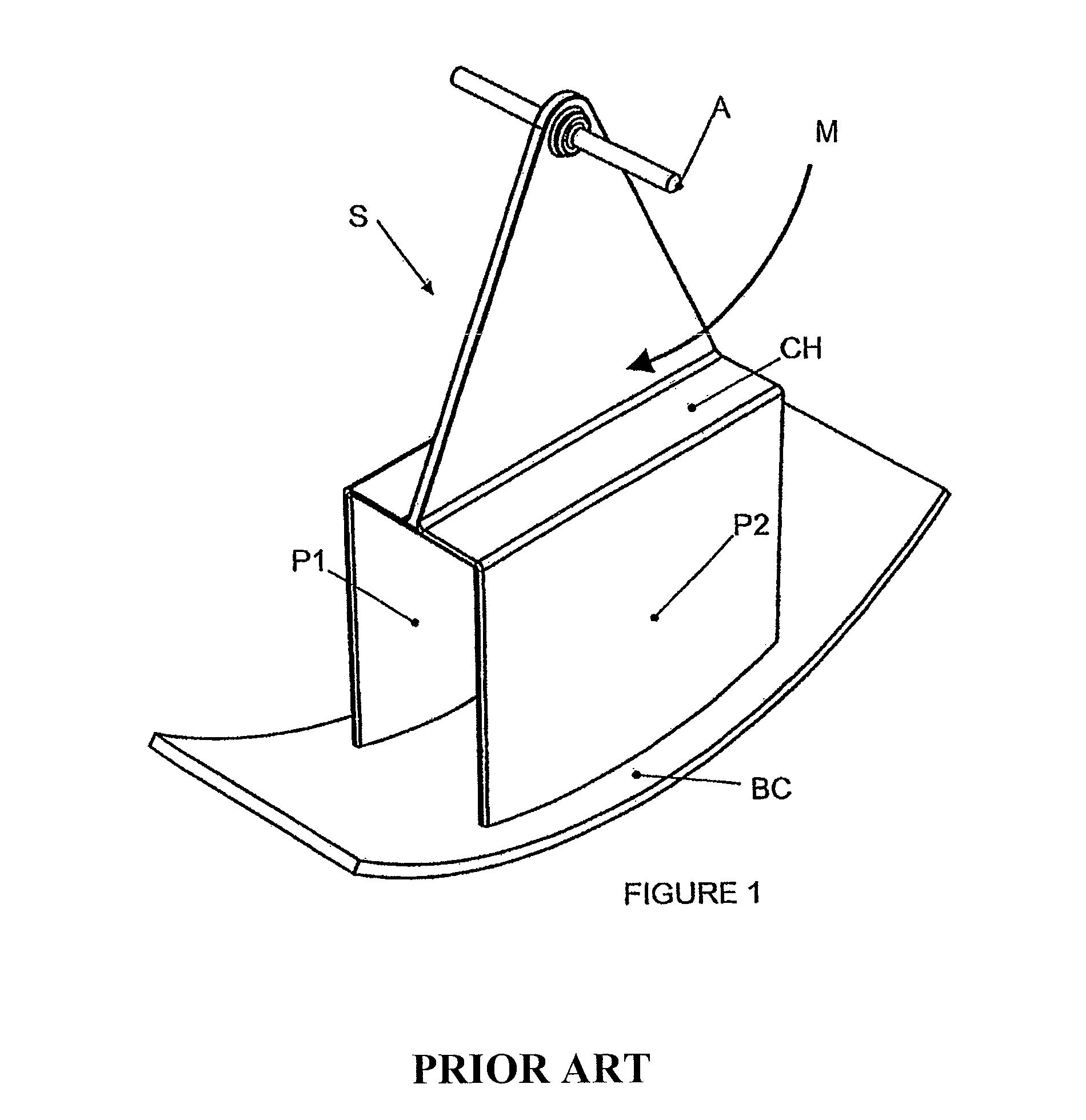
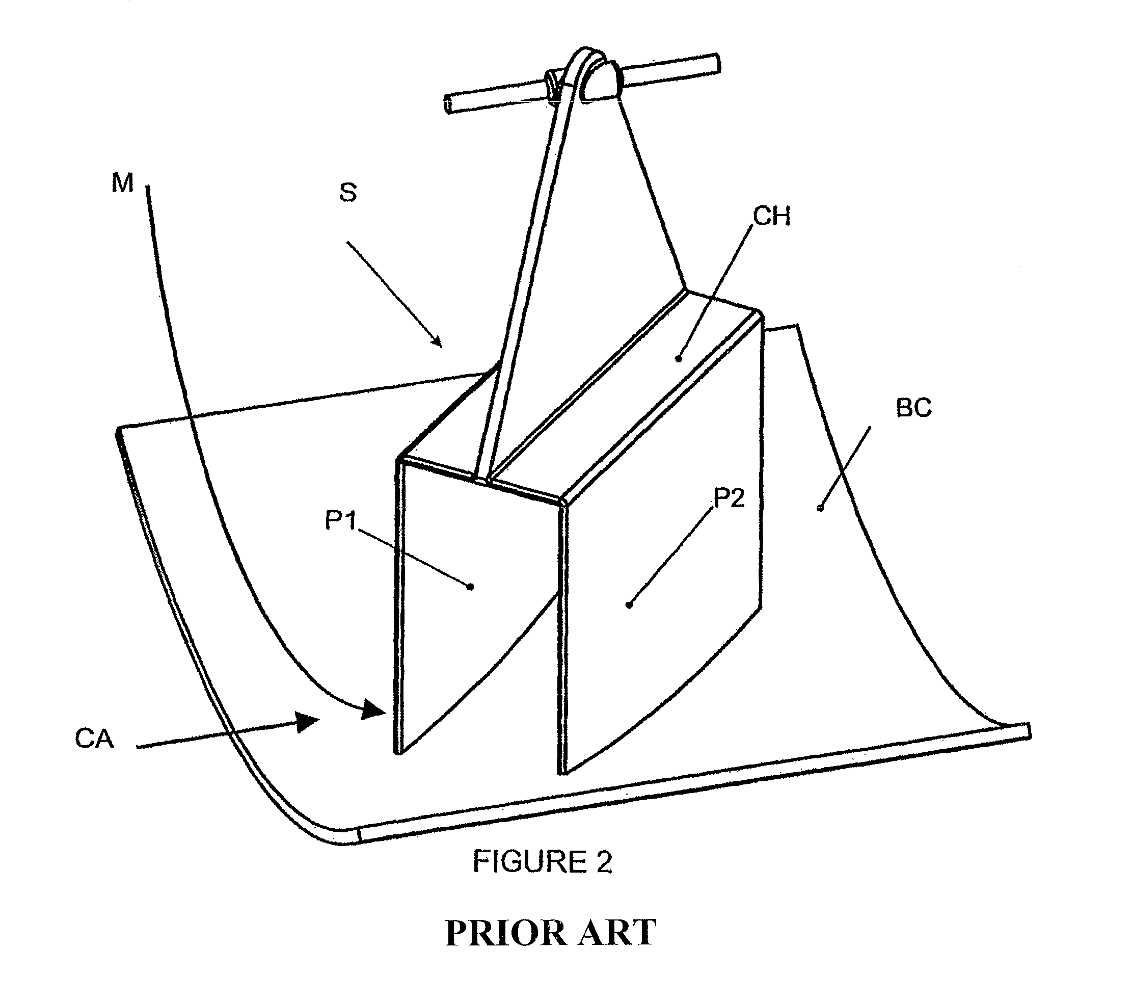
[0042]As hereinbefore described, FIGS. 1 and 2 illustrate examples of PRIOR ART cross-belt samplers S operating in conjunction with a belt conveyor BC.

[0043]The cutter head CH has a pair of parallel side plates P1, P2 which delimit the sample (not shown) taken from material being conveyed on the belt conveyor BC.

[0044]The sampler S in FIG. 1 has its axis of rotation A parallel to the central axis of the belt conveyor BC and the side plates P1, P2 are parallel to the motion M of the cutter head CH; while the sampler S in FIG. 2 has its side plates P1, P2 at an angle, eg., 45° or 60° to the motion M of the cutter head CH relative to the belt conveyor BC.

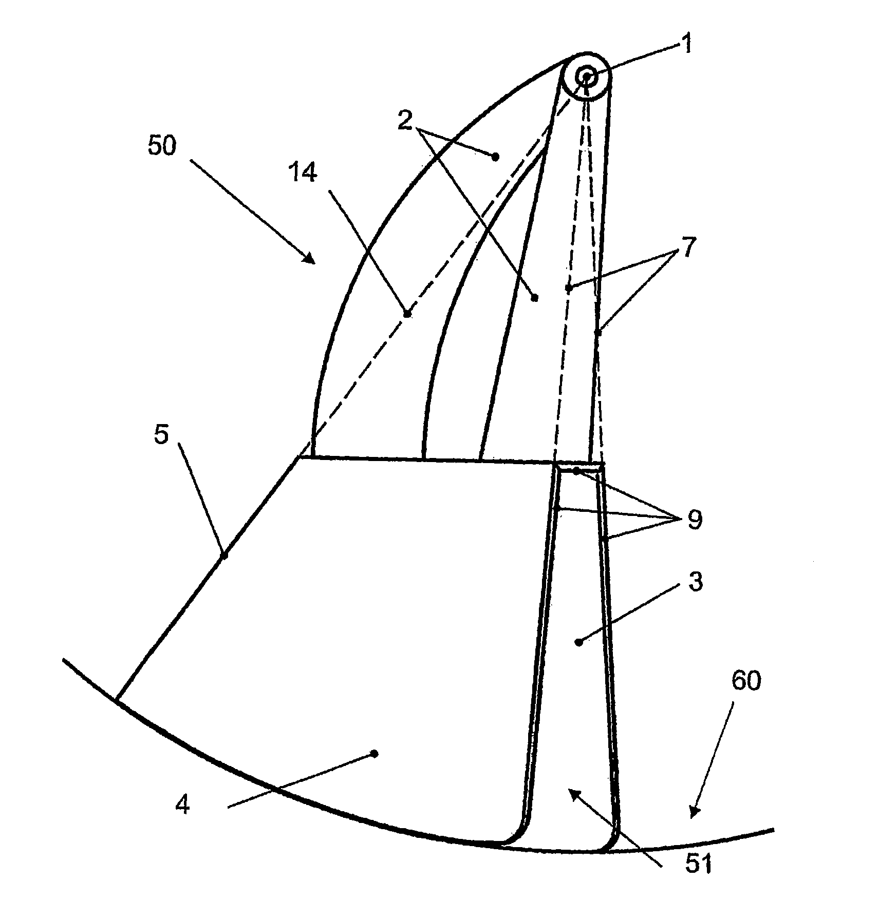
[0045]FIG. 3 is a side elevational view of the cutter head 50, of the present invention, in a position such that the axis of rotation 1 of the device is perpendicular to the plane of the drawing. The cutter head is attached to the shaft 1 by suitable arms 2 fixed to the shaft 1 and to the body of the cutter head 50. The sampler opening...


PUM

PropertyMeasurementUnit
angleaaaaaaaaaa
angleaaaaaaaaaa
acute anglesaaaaaaaaaa

Abstract

A cross-belt sampler (100) for material (70) on a belt-conveyor (60) has a cutter head (50), where the cutting edges (9) of the side plates (3,4) lie on lines co-incident with the axis of rotation (1) of the cutter head (50). The rear plate (5) lies on a plane parallel to the axis of rotation (1) and a truncated plate (6) eliminates a sharp corner in which the material (70) may be compacted. The axis of rotation (1) of the cutter head (50) is offset a distance (28) relative to the longitudinal axis of the belt conveyor (60).

Description

CROSS-REFERENCE TO RELATED APPLICATION[0001]This application is a Section 371 of International Application No. PCT / AU2007 / 000847, filed Jun. 18, 2007, which was published in the English language on Dec. 27, 2007 under International Publication No. WO 2007 / 147201 A1, and the disclosure of which is incorporated herein by reference.BACKGROUND OF THE INVENTION[0002]1. Field of the Invention[0003]The device described herein is a new design for a sampler head or sample cutter for the extraction of representative sample increments from a material stream conveyed on a belt conveyor. The sampler is of a type generally called a cross-belt sampler, but is also known as a go-belt sampler or a hammer sampler.[0004]The new design corrects the technical faults that are present in the known designs. The novel design principle for the sample cutter geometry can in fact be used to show that all the known designs for cross-belt sampler cutters, with one exception, take a sample that is not representat...

Claims


Application Information

Patent Timeline
Patent Type & Authority Patents(United States)
IPC IPC(8): G01N1/20G01N1/08
CPCG01N1/08G01N1/20G01N35/021G01N2001/2028G01N2001/2092
Inventor LYMAN, GEOFFREY JOHN
Owner LYMAN GEOFFREY JOHN
Why Eureka
Try Eureka