
Method and apparatus for providing full logical connectivity in MPLS networks

Active Publication Date: 2012-04-10
RPX CORP
View PDF13 Cites 281 Cited by
  • Summary
  • Abstract
  • Description
  • Claims
  • Application Information

AI Technical Summary

Benefits of technology

[0003]Various deficiencies in the prior art are addressed through the invention of a method and apparatus for configuring logical connectivity for a network comprising a plurality of nodes. A method includes determining a physical topology of the network, determining a set of LSP paths based on the physical topology of the network, and determining a set of LSPs using the set of LSP paths, where the set of LSPs includes a plurality of LSPs adapted for providing full logical connectivity between the nodes of the network. The physical topology is determined using information indicative of physical connectivity between nodes of the network. The set of LSP paths includes, for each pair of nodes in the network, at least two logical paths between the nodes of the node pair. The set of LSPs includes a plurality of LSPs adapted for providing full logical connectivity between the nodes of the network. The full logical connectivity between the nodes of the network may be maintained in response to physical topology change events, such as addition of nodes to the network removal of nodes from the network, and the like.

Problems solved by technology

Disadvantageously, however, determining and provisioning of LSPs in existing MPLS networks is currently performed manually via a user interface of a network management system (NMS) by individually determining and provisioning each LSP by using the Command Line Interface (CLI) access point on individual nodes.

Method used


Image

  • Method and apparatus for providing full logical connectivity in MPLS networks
  • Method and apparatus for providing full logical connectivity in MPLS networks
  • Method and apparatus for providing full logical connectivity in MPLS networks

Examples


Embodiment Construction

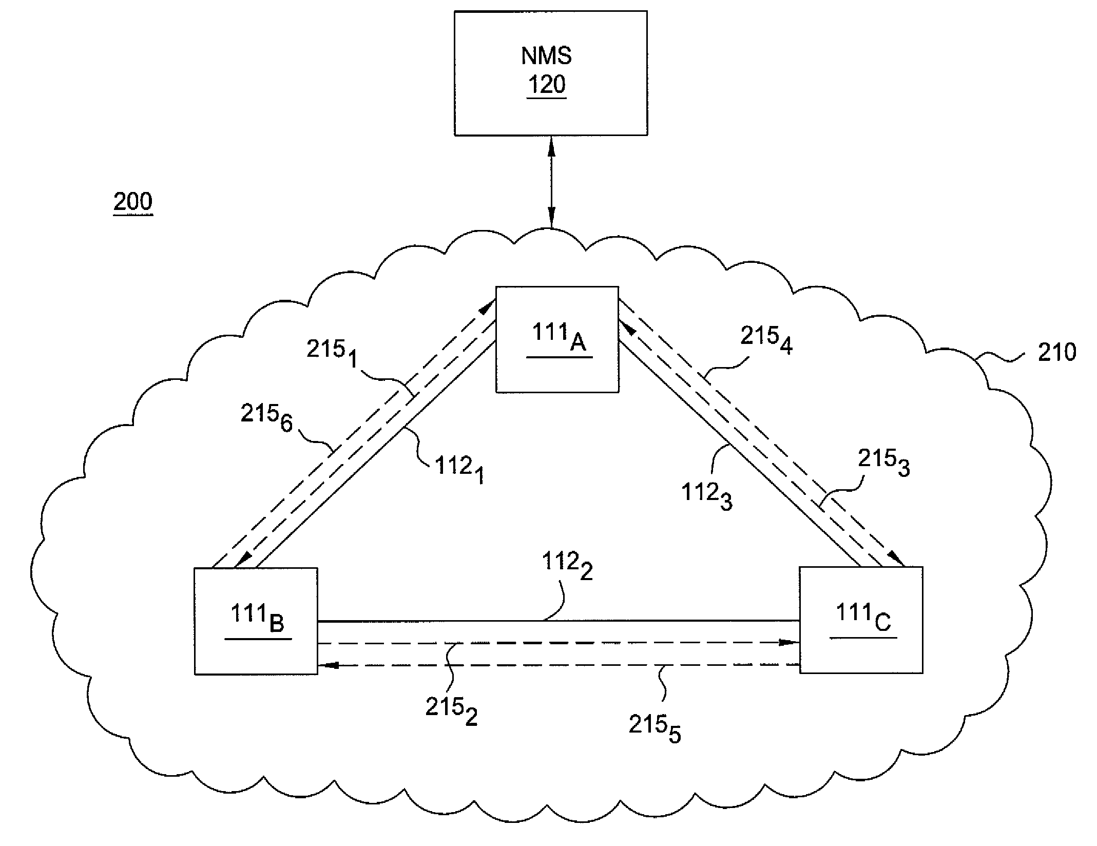
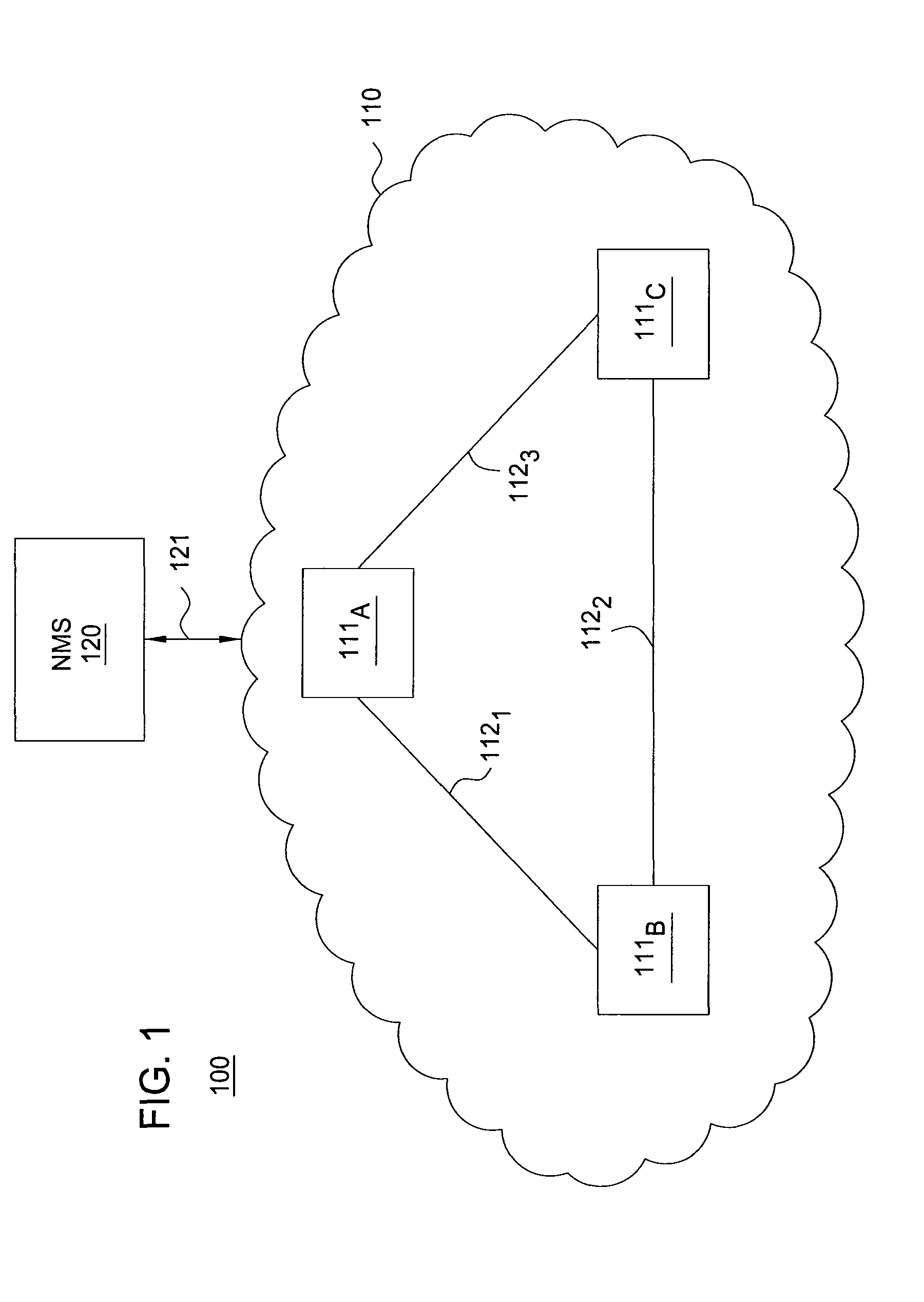
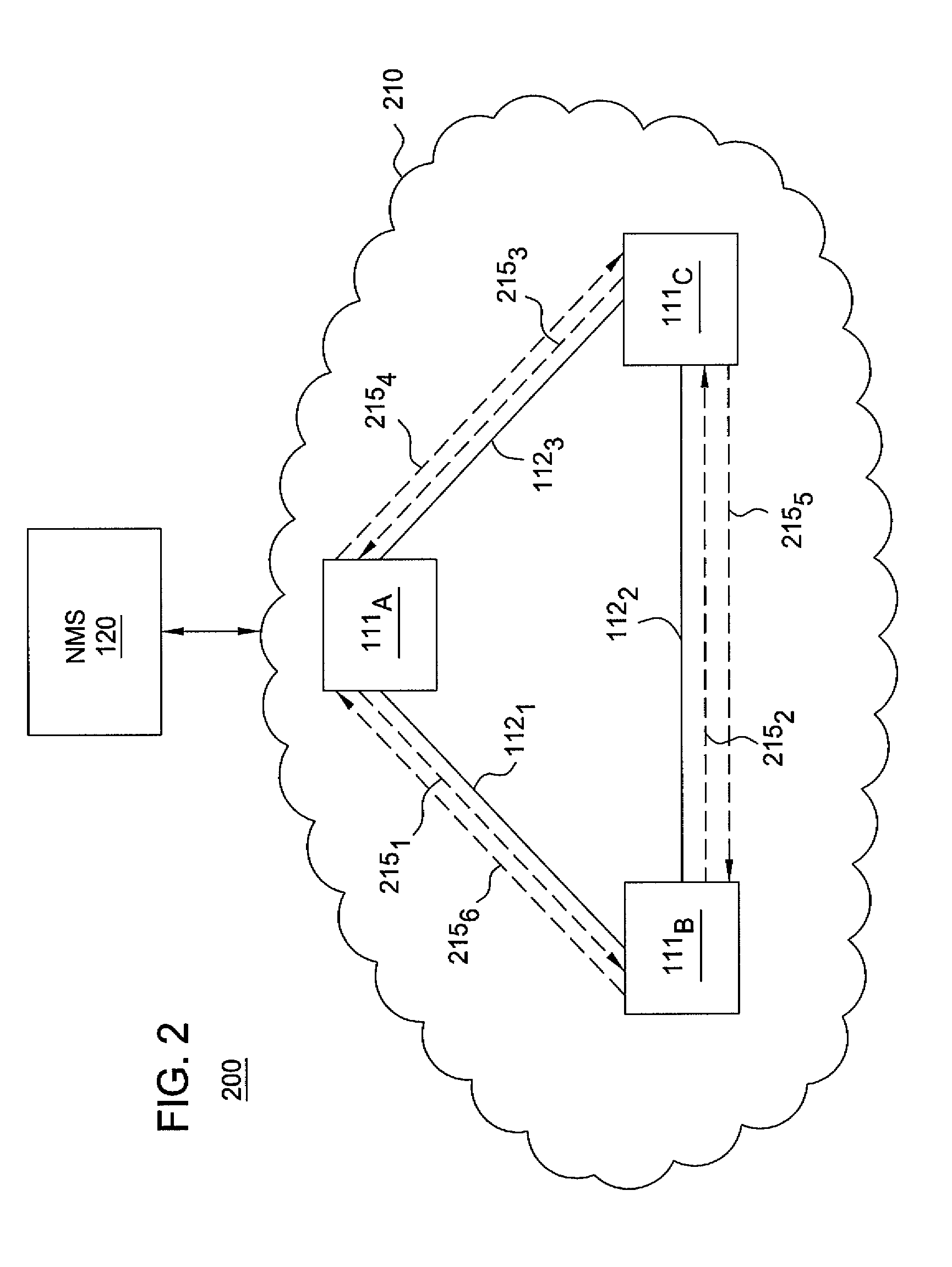
[0013]The present invention determines full logical connectivity within an MPLS network. The full logical connectivity is determined using the physical topology of the network (e.g., based on information indicative of the physical connectivity between nodes of the MPLS network). The physical topology may be used to determine a set of LSP paths for the MPLS network. The set of LSP paths for the MPLS network may then be used to determine a set of LSPs adapted to provide full logical connectivity within the MPLS network. This enables provisioning of full logical connectivity within the MPLS network. Although primarily depicted and described herein within the context of MPLS networks, logical connectivity determination / provisioning functions depicted and described herein may be applied to other networks.

[0014]FIG. 1 depicts a high-level block diagram of a communication network architecture. Specifically, communication network architecture 100 includes a communication network (CN) 110 an...


PUM


Abstract

The invention includes a method and apparatus for configuring logical connectivity for a network comprising a plurality of nodes. A method includes determining a physical topology of the network, determining a set of LSP paths based on the physical topology of the network, and determining a set of LSPs using the set of LSP paths, where the set of LSPs includes a plurality of LSPs adapted for providing full logical connectivity between the nodes of the network. The physical topology is determined using information indicative of physical connectivity between nodes of the network. The set of LSP paths includes, for each pair of nodes in the network, at least two logical paths between the nodes of the node pair. The set of LSPs includes a plurality of LSPs adapted for providing full logical connectivity between the nodes of the network. The full logical connectivity between the nodes of the network may be maintained in response to physical topology change events, such as addition of nodes to the network removal of nodes from the network, and the like.

Description

FIELD OF THE INVENTION[0001]The invention relates to the field of communication networks and, more specifically, to multi-protocol label switching (MPLS) networks.BACKGROUND OF THE INVENTION[0002]Multiprotocol Label Switching (MPLS) enables efficient delivery of a wide variety of differentiated, end-to-end services. MPLS supports delivery of such services using label switched paths (LSPs). Depending on different factors, hundreds or even thousands of LSPs may be provisioned in a given MPLS network. As network conditions change, LSPs provisioned in a given MPLS network often need to be changed. Disadvantageously, however, determining and provisioning of LSPs in existing MPLS networks is currently performed manually via a user interface of a network management system (NMS) by individually determining and provisioning each LSP by using the Command Line Interface (CLI) access point on individual nodes.SUMMARY OF THE INVENTION[0003]Various deficiencies in the prior art are addressed thro...

Claims


Application Information

Patent Timeline
Patent Type & Authority Patents(United States)
IPC IPC(8): H04L12/28H04L45/02H04L45/50H04L45/42
CPCH04L41/0803H04L45/02H04L45/50H04L41/12H04L43/0811
Inventor ABU-HAMDEH, RATEBCALIPPE, JOELWANG, ZIHUANG
Owner RPX CORP
Learn More