
Telescopic fracturing isolation sleeve

a technology of isolation sleeves and telescopic fracturing, which is applied in the direction of drilling casings, drilling pipes, borehole/well accessories, etc., can solve the problems of affecting the sealing and other parts of the device, sleeve to become lodged in position, and difficult removal in the reverse upward direction

Active Publication Date: 2012-04-17
T 3 PROPERTY HLDG INC
View PDF12 Cites 2 Cited by
  • Summary
  • Abstract
  • Description
  • Claims
  • Application Information

AI Technical Summary

Benefits of technology

The solution allows for reliable and efficient removal of the isolation sleeve across various wellhead assembly configurations, accommodating different stack heights and pressure ratings, simplifying the process by enabling telescopic adjustment and independent actuation, thus overcoming the challenges of extreme pressures and varying wellhead assembly designs.

Problems solved by technology

However, the fracturing process can involve abrasive fluids that can harm seals and other portions of the devices in the wellhead assembly.
However, removal in the reverse upward direction can be difficult.
After a fracturing operation, the sleeve can become hard to remove manually due to the extreme pressures and can cause the sleeve to become lodged in position.
However, as soon as the seals extend beyond the sealed internal bore, the pressure dissipates and can longer be used as a medium to continue pushing out the isolation sleeve.
Thus, the force to remove the remainder of the isolation sleeve can become a challenge when a drilling rig is not present when the sleeve has to be removed manually.
The complexities are extended when different wells have different wellhead assembly stack heights due to different pressure ratings.

Method used


Image

  • Telescopic fracturing isolation sleeve
  • Telescopic fracturing isolation sleeve
  • Telescopic fracturing isolation sleeve

Examples


Embodiment Construction

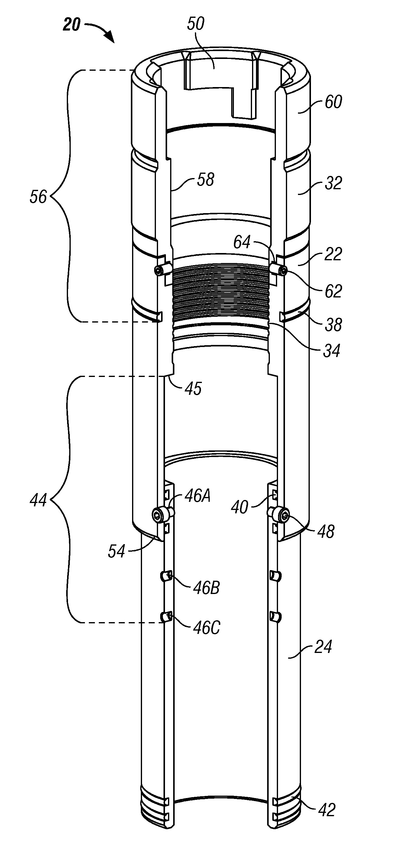
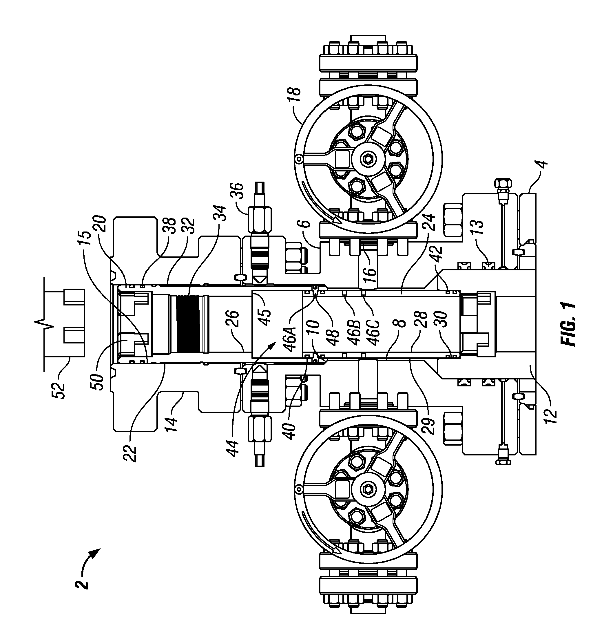
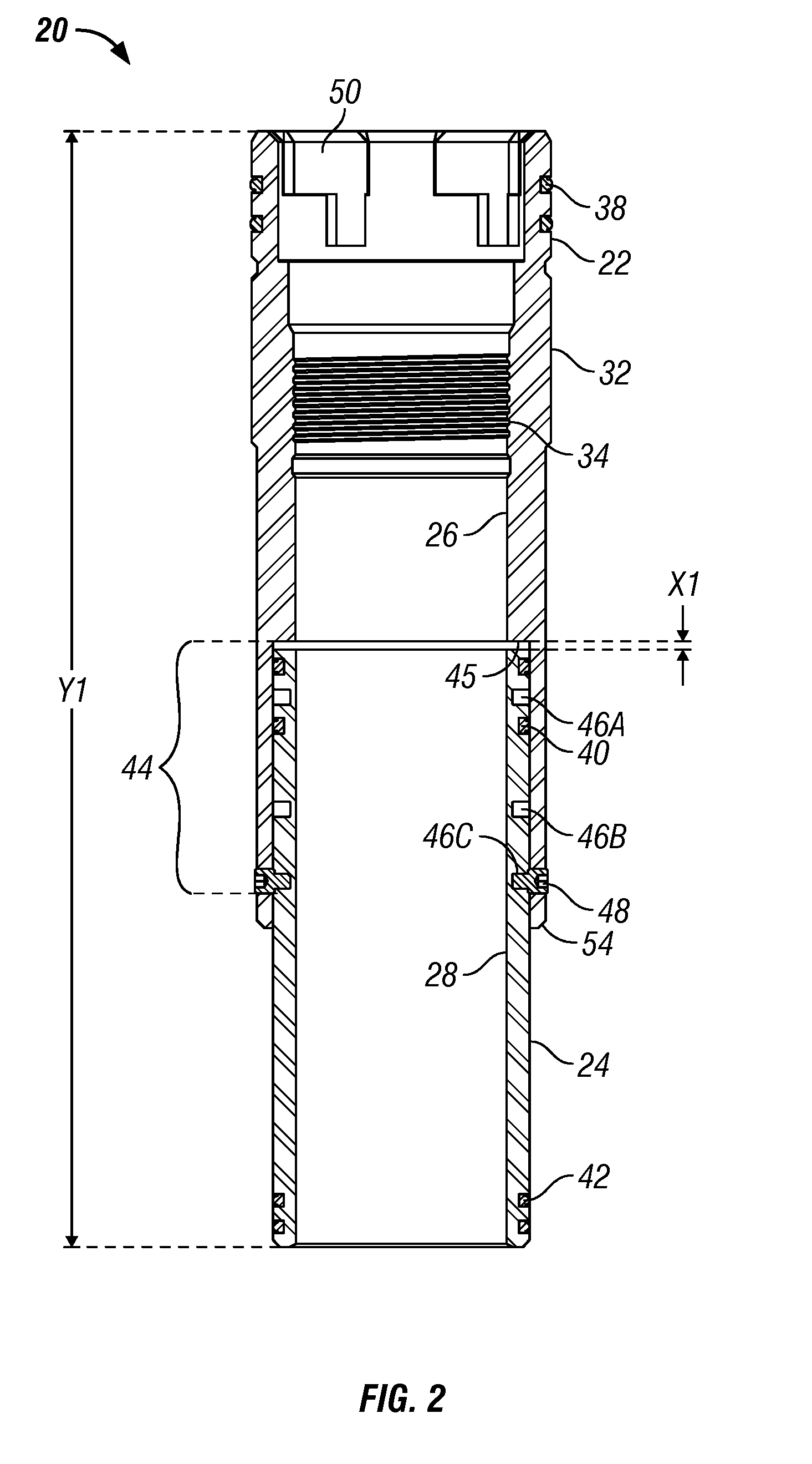
[0033]The Figures described above and the written description of specific structures and functions below are not presented to limit the scope of what Applicants have invented or the scope of the appended claims. Rather, the Figures and written description are provided to teach any person skilled in the art to make and use the inventions for which patent protection is sought. Those skilled in the art will appreciate that not all features of a commercial embodiment of the inventions are described or shown for the sake of clarity and understanding. Persons of skill in this art will also appreciate that the development of an actual commercial embodiment incorporating aspects of the present inventions will require numerous implementation-specific decisions to achieve the developer's ultimate goal for the commercial embodiment. Such implementation-specific decisions may include, and likely are not limited to, compliance with system-related, business-related, government-related, and other ...


PUM


Abstract

The disclosure provides a fracturing isolation sleeve for a wellhead assembly including a fracturing adapter and tubing head. In at least one embodiment, the sleeve can telescopic to different lengths to fit different assemblies without necessitating switching the sleeve or portions thereof. The sleeve can be coupled to the wellhead assembly by threaded and non-threaded connections. The sleeve upper portion can be threadably engaged with the wellhead assembly, and / or the sleeve lower portion can be threadably engaged with a packoff bushing rotationally coupled to the wellhead assembly through an anti-rotation mechanism. Further, the sleeve can include a retaining nut to be threadably engaged with the wellhead assembly without necessarily rotating the sleeve upper or lower portions. The sleeve can be also coupled with the wellhead assembly through a mandrel coupled to the sleeve having an actuating cam surface to actuate a lock ring with the wellhead assembly.

Description

CROSS REFERENCE TO RELATED APPLICATIONS[0001]This application claims the benefit of U.S. Provisional Appl. No. 61 / 033,329, filed Mar. 3, 2008, and is incorporated herein by reference.STATEMENT REGARDING FEDERALLY SPONSORED RESEARCH OR DEVELOPMENT[0002]Not applicable.NAMES OF PARTIES TO A JOINT RESEARCH AGREEMENT[0003]Not applicable.REFERENCE TO APPENDIX[0004]Not applicable.BACKGROUND[0005]1. Field of the Invention The disclosure relates to pile oil field equipment, and particularly for oil field equipment designed to drilling and production of hydrocarbons from oil and gas wells.[0006]2. Description of Related Art[0007]It is a common practice when drilling and producing an oil or gas well to insert casing into the drilled hole and mount a wellhead assembly above ground to the casing. The wellhead assembly is a series of stacked devices, each having an internal bore aligned with the casing. For example, a casing head is mounted to the casing, followed by a tubing head with a packoff ...

Claims


Application Information

Patent Timeline
Patent Type & Authority Patents(United States)
IPC IPC(8): E21B28/00E21B19/00
CPCE21B17/07E21B33/068
Inventor KOLEILAT, BASHIRGRESHAM, SEANCAIN, DAVID
Owner T 3 PROPERTY HLDG INC
Learn More