Illuminated continuously rotatable dual magnification mirror

a mirror and magnification technology, applied in the field of mirrors, can solve the problems of inconvenient positioning of one's face sufficiently close to an existing flat mirror, and the general deformation of the person's vision with ag

Active Publication Date: 2012-04-24
ZADRO INC
View PDF10 Cites 95 Cited by
  • Summary
  • Abstract
  • Description
  • Claims
  • Application Information

AI Technical Summary

Benefits of technology

[0025]The novel design and construction of an illuminated dual magnification mirror according to the present invention provides an equally bright, uniform illumination pattern in object fields located in front of both mirror plates. Moreover, the novel design and construction of the mirror according to the present invention advantageously enables the mirror frame to be continuously rotated to thus position the 1× or 5× magnifying mirror plates at any desired angle with respect to the mirror frame support yoke, without the possibility of twisting or breaking electrical illumination wires which power the illumination source within the mirror frame.

Problems solved by technology

In some circumstances, however, it is not convenient to position one's face sufficiently close to an existing flat mirror to provide an image which is sufficiently large to enable a desired personal grooming task to be easily performed.
However, since a person's vision generally degrades with age, there is an accompanying need for a mirror of selectable magnification which can supplement existing larger mirrors to enable a person to see image details required to perform personal care functions.

Method used


Image

  • Illuminated continuously rotatable dual magnification mirror
  • Illuminated continuously rotatable dual magnification mirror
  • Illuminated continuously rotatable dual magnification mirror

Examples


Embodiment Construction

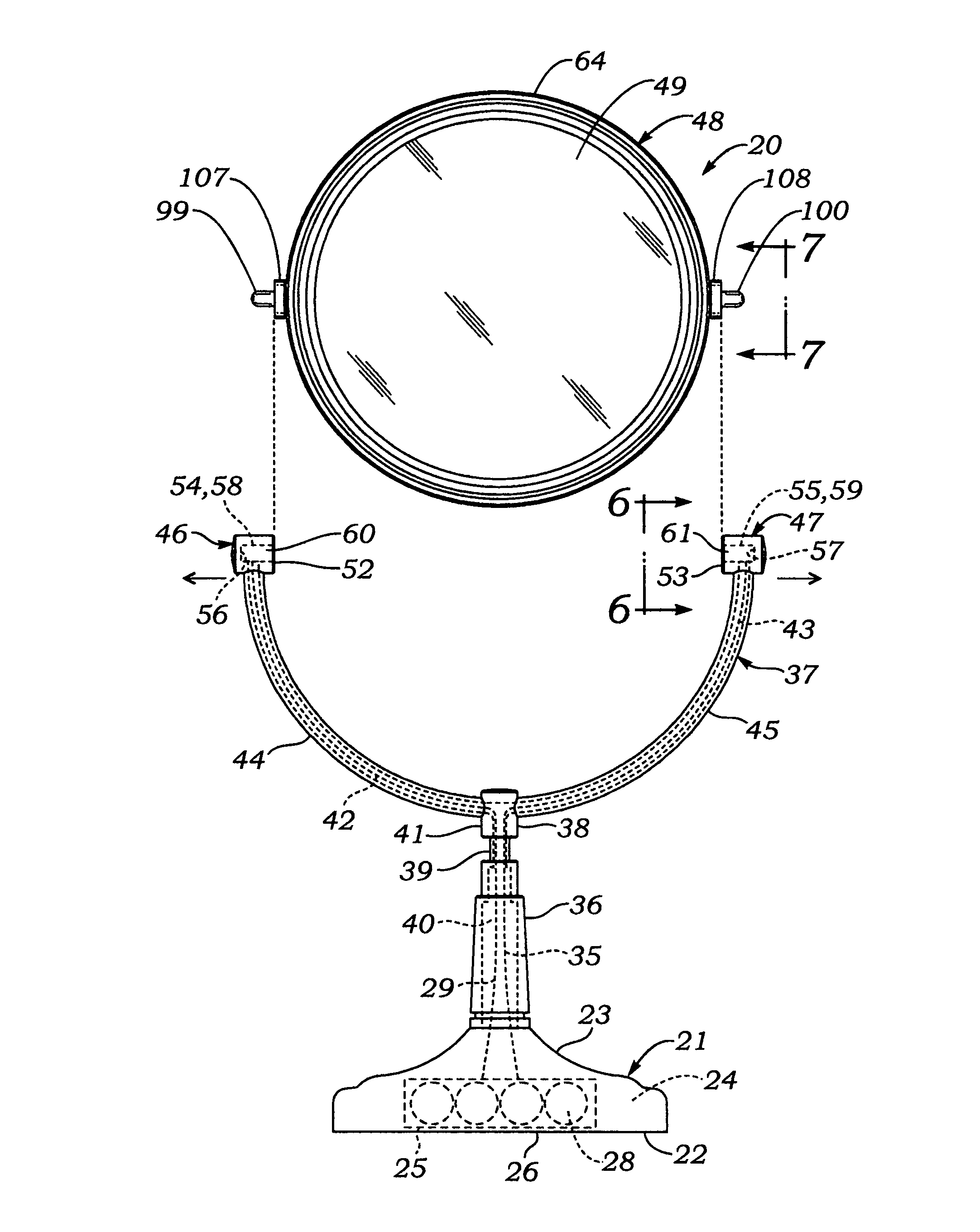
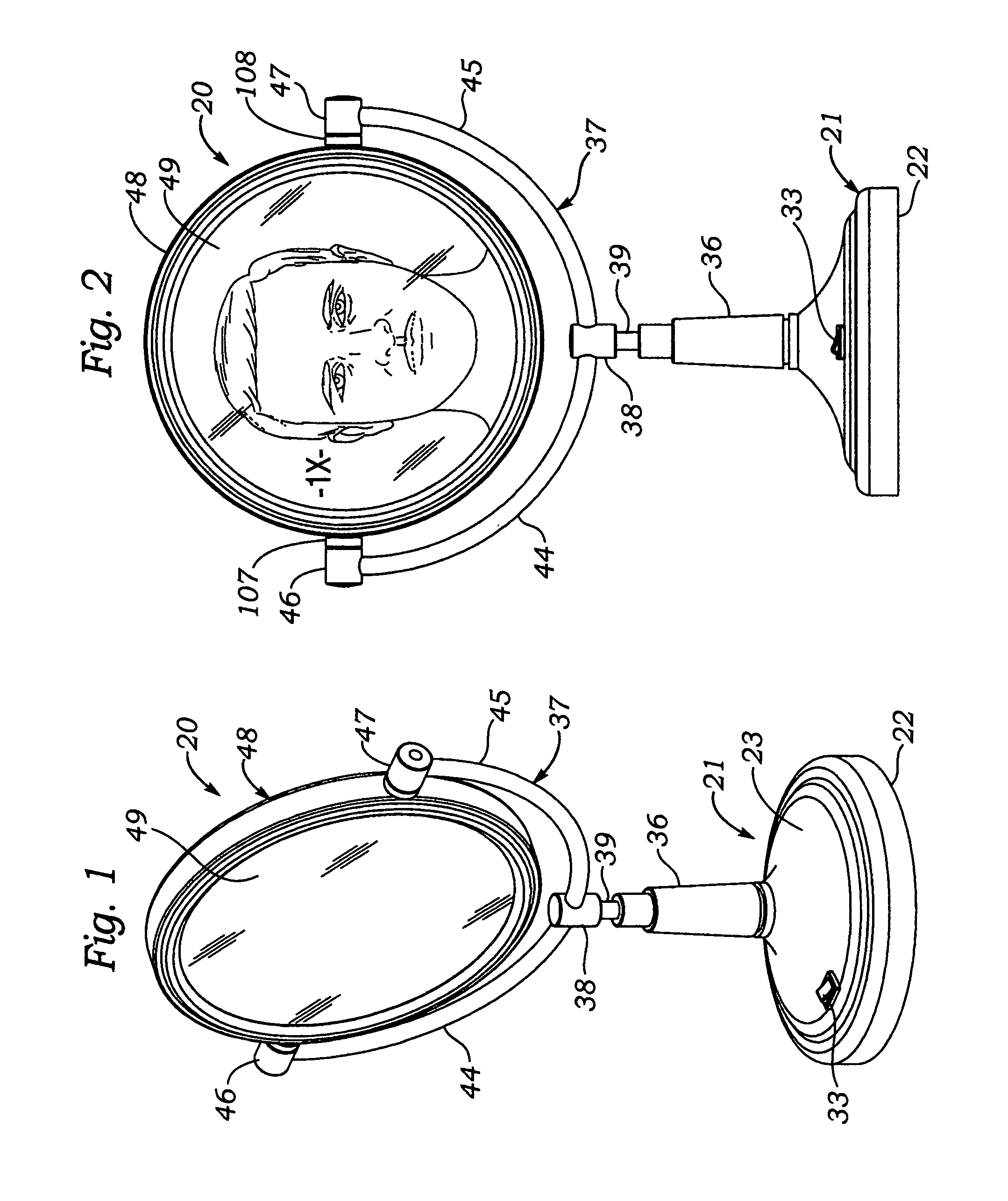
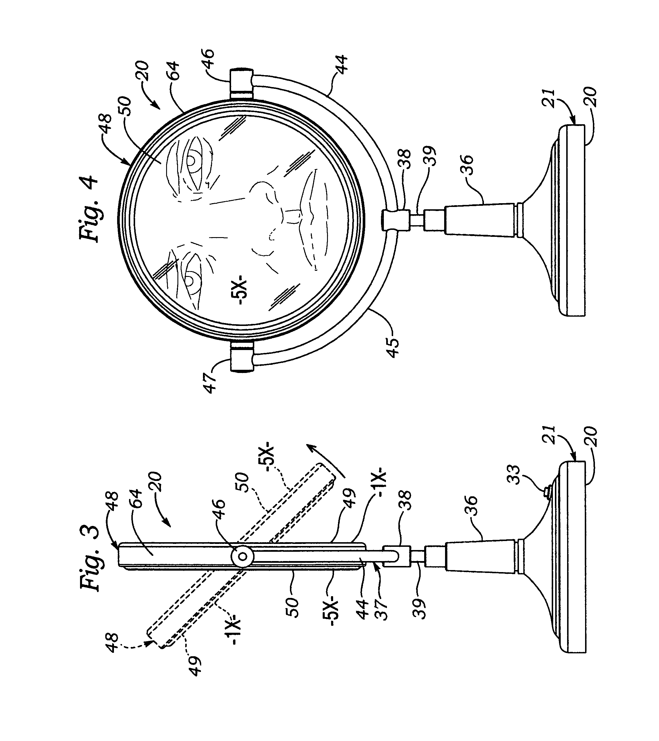
[0042]FIGS. 1-13 illustrate an illuminated continuously rotatable dual magnification mirror according to the present invention.

[0043]Referring first to FIGS. 1-4, it may be seen that an illuminated continuously rotatable dual magnification mirror 20 according to the present invention includes a hollow, circularly-shaped base 21 which has a flat lower wall 22 for placement on a supporting surface such as a table top. As may be seen best by referring to FIGS. 9 and 10, base 21 has located between lower wall 22 and an upper wall 23 thereof a hollow interior space 24 which contains a battery holder 25 that is accessible via a rectangularly-shaped trap door 26 which snaps into a similarly-shaped access port 27 disposed through the lower wall 22 of the base.

[0044]As shown in FIGS. 9 and 11, battery holder 25, which in an example embodiment was constructed to hold 4 A-A batteries connected in series, has a first, common terminal 28 to which is electrically connected a flexible insulated, c...


PUM


Abstract

A mirror for facilitating appearance related functions includes a circular ring-shaped frame holding therein back-to-back reflective mirror plates having different magnification factors, e.g. 1× and 5×, each plate having a circular central imaging reflective area and an outer concentric light transmissive window area. Continuously rotatable pivot joints support the frame between opposed arms of a yoke protruding upwardly from a stanchion and base for placement on a table, or an arm and wall bracket for mounting on a wall, enabling the frame to be rotated to interchangeably orient 1× and 5× mirror plates in a forward facing use position. A ring-shaped, printed circuit board with circumferentially spaced apart light emitting diodes (LED's) protruding radially outwards of an outer circumferential edge of the board is located between inner facing surfaces of the mirror plates. Illumination of objects in front of the mirror plates is effected by direct LED rays emitted forwardly through the light transmissive windows, and intensified by indirect LED rays reflected from reflective inner facing surfaces of the mirror plates. Electrical power is supplied to the LED's from a battery power supply in the base of the mirror by electrically conductive pins which protrude radially outwards from opposite sides of the frame, the pins being rotatably supported in electrically conductive cups located in opposed arms of the yoke, the cups being connected to the power supply via wires disposed through the yoke arms and stanchion to the power supply.

Description

BACKGROUND OF THE INVENTION[0001]A. Field of the Invention[0002]The present invention relates to mirrors of the type used by people to facilitate performance of personal appearance related functions such as shaving, applying cosmetics and the like. More particularly, the invention relates to a versatile free-standing mirror which includes a base for supporting the mirror on a horizontal surface such as that of a table top, and a frame containing back-to-back mirror plates of different magnification factors, the frame being pivotably mounted to the base by a continuously rotatable joint and containing an internal illumination source that is effective in illuminating object fields in front of both mirror plates.[0003]B. Description of Background Art[0004]Certain aspects of a person's appearance are best attended to by observing a person's image in a relatively large “wide angle” mirror, which has a flat reflective surface that provides a unity or “1×” magnification. Mirrors of this ty...

Claims


Application Information

Patent Timeline
Patent Type & Authority Patents(United States)
IPC IPC(8): F21V33/00F21V21/26
CPCA45D42/10F21V33/004F21Y2115/10
Inventor ZADRO, ZLATKO
Owner ZADRO INC
Why Eureka
Try Eureka