Spouted-fluidized bed-type olefin polymerization reactor

a technology of olefin polymerization and fluidized bed, which is applied in the direction of chemical/physical/physical-chemical stationary reactors, chemical apparatus and processes, etc., can solve the problems of easy flow defects, increased gas flow rate, and small particle size of polyolefin particles obtained by polymerization, and achieves low blowing amount.

Active Publication Date: 2012-04-24
SUMITOMO CHEM CO LTD
View PDF107 Cites 0 Cited by
  • Summary
  • Abstract
  • Description
  • Claims
  • Application Information

AI Technical Summary

Benefits of technology

[0011]It is therefore an object of the present invention to provide an olefin polymerization reactor in which fluidization can be conducted at a comparatively low blowing rate even when polyolefin particles of a large diameter and high cohesion ability are handled and also to provide a polyolefin production system equipped with such an olefin polymerization reactor. Another object of the invention is to provide a polyolefin production process which uses such an olefin polymerization reactor or polyolefin production system.
[0030]The polyolefin production process according to the invention may include the steps of continuously feeding olefin to the olefin polymerization reactor through the gas inlet orifice and the plurality of through holes and at the same time continuously removing a gas containing unreacted olefin from the olefin polymerization reactor and returning the removed gas to the olefin polymerization reactor; and cooling part or all of the removed gas so as to obtain an olefin-containing condensate. In this case, it is preferred that the condensate be fed to a spout portion formed within the reaction zone of the olefin polymerization reactor. As a result, latent heat of vaporization of the condensate can be used and heat can be efficiently withdrawn by the condensate from the olefin polymerization reactor. Further, when the olefin polymerization reactor is equipped with the first conical baffle, the condensate may be fed to the lower portion the first conical baffle. This has the advantage of enabling a condensate feeding line to be installed using the first conical baffle as a fitting.

Problems solved by technology

The major reason therefor is that the polyolefin particles obtained by polymerization have a small particle size and are unsuitable for handling during molding.
However, the problem is that in order to handle polyolefin particles having a larger diameter (an average particle diameter of about 2 to 5 mm) in the conventional fluidized bed apparatus, the gas flow rate is increased in order to fluidize the particles.
The problem arising in such cases is that flow defects easily occur in the conventional fluidized bed-type apparatus and the gas flow rate necessary to enhance the fluidization increases.

Method used


Image

  • Spouted-fluidized bed-type olefin polymerization reactor
  • Spouted-fluidized bed-type olefin polymerization reactor
  • Spouted-fluidized bed-type olefin polymerization reactor

Examples


first embodiment

Polyolefin Production System

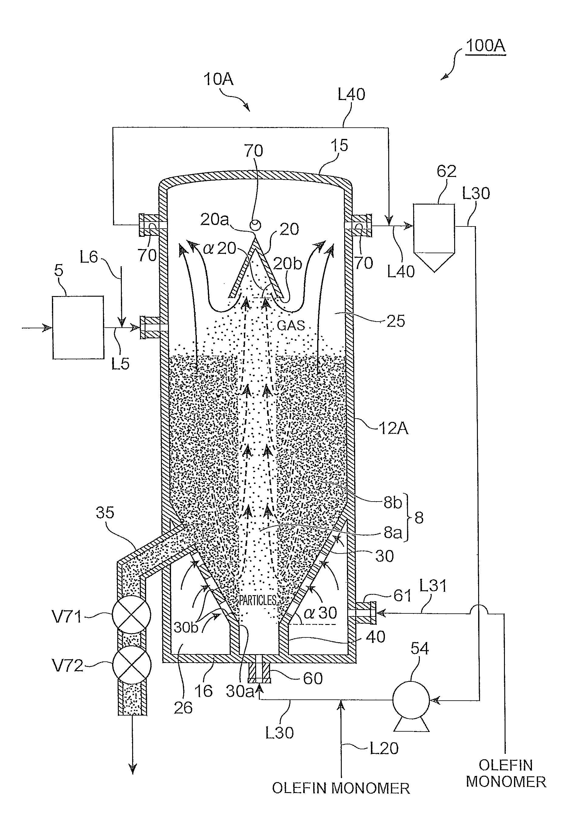
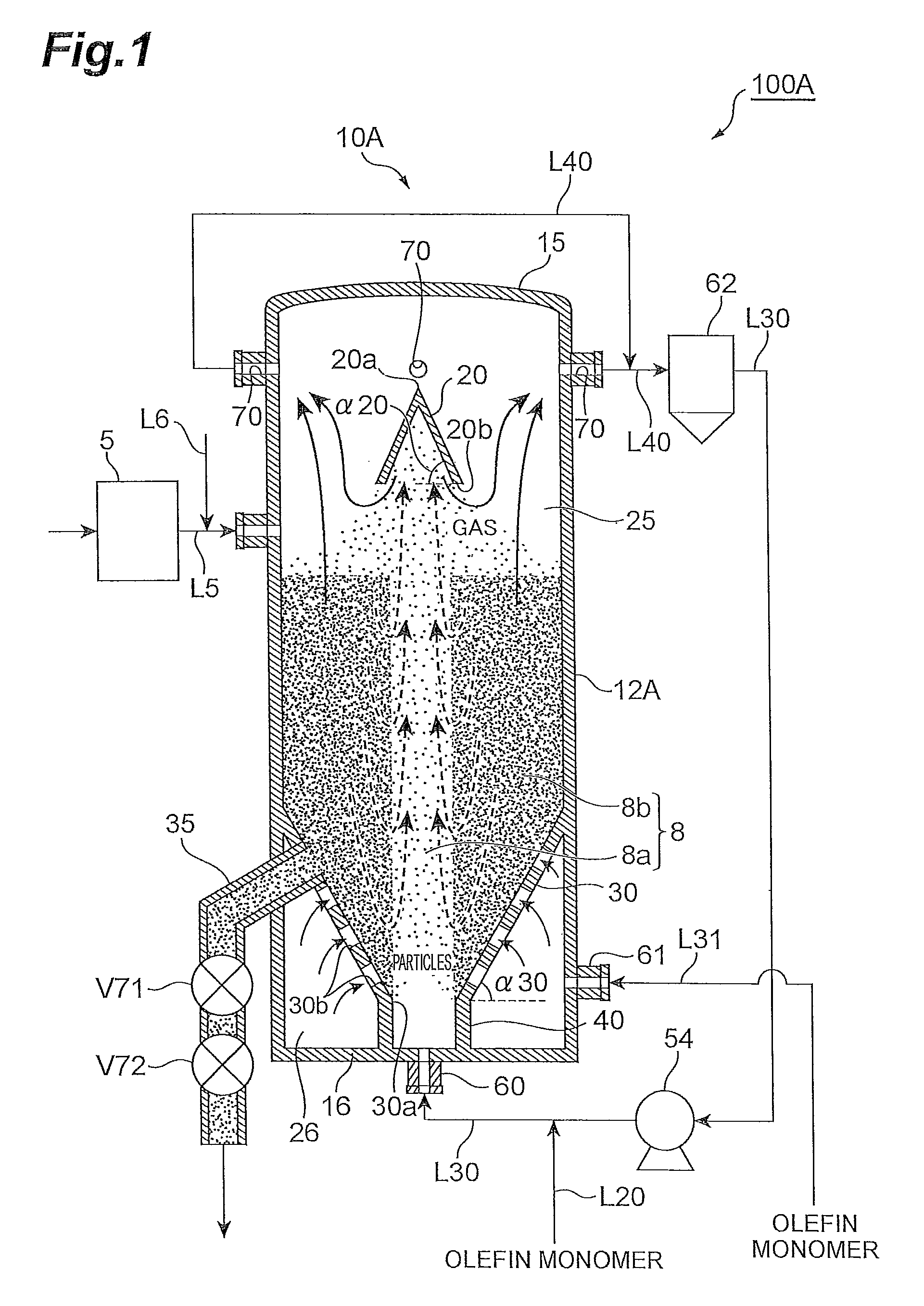
[0047]FIG. 1 shows a polyolefin production system 100A according to the first embodiment. This production system 100A includes an olefin prepolymerization reactor 5 and an olefin polymerization reactor 10A which is connected as a subsequent stage to the olefin prepolymerization reactor 5.

[0048]Olefin Prepolymerization Reactor

[0049]The olefin prepolymerization reactor 5 polymerizes olefin in the presence of an olefin polymerization catalyst to form polyolefin particles.

[0050]Examples of the olefin prepolymerization reactor 5 include, but are not limited to, slurry polymerization reactors, bulk polymerization reactors, stirred tank-type gas phase polymerization reactors, and fluidized bed-type gas phase polymerization reactors. Any one of these reactors may be used alone, a plurality of reactors of the same type may be used in combination, or two or more reactors of differing types may be used in combination.

[0051]Slurry polymerization reactors that may be ...

second embodiment

[0147]A production system 100B shown in FIG. 3 has an olefin prepolymerization reactor 5 and an olefin polymerization reactor 10B. The olefin polymerization reactor 10B differs from the above-described reactor 10A in having a draft tube T1 disposed within the reaction zone 25. By using the draft tube T1, it is possible to form within the reaction zone 25 a spouted bed that has excellent stability and can further reduce the pressure loss.

[0148]The reactor 10B uses the draft tube T1 disposed within the reaction zone 25, enabling to obtain the gas composition within the draft tube T1 that is different from the gas composition outside the draft tube T1. The reactor 10B is equipped with a pipe L25 communicating with the inside of the draft tube T1, and a gas or a liquid is fed into the draft tube T1 through this pipe. For example, by obtaining a gas composition inside the draft tube T1 that has a hydrogen content lower than that in the gas composition outside the draft tube, it is possib...

third embodiment

[0149]A preferred arrangement of the polyolefin production system which employs a bulk polymerization reactor as the olefin prepolymerization reactor and employs an ejector system as the transferring means is described in detail while referring to FIG. 4. The polyolefin production system 100C shown in FIG. 4 includes a bulk polymerization reactor 5 and an olefin polymerization reaction 10C having at the interior both top and bottom reaction zones 25.

[0150]The bulk polymerization reactor 5 polymerizes an olefin in a liquid phase containing an olefin polymerization catalyst, thereby forming polyolefin particles. The polyolefin particles formed in the bulk polymerization reactor 5 pass together with liquid olefin through a line L5, and are fed to the olefin polymerization reactor 10C. A nozzle 68 for feeding a slurry to the top reaction zone 25 is provided, as shown in FIG. 4, at a position lower than the powder level 85 of the spouted bed. When the slurry is fed into the reaction zone...


PUM

PropertyMeasurementUnit
particle diameteraaaaaaaaaa
temperatureaaaaaaaaaa

Abstract

An olefin polymerization reactor according to the present invention comprises: a vertically extending cylinder; a decreasing diameter portion on the cylinder, having an inside diameter that decreases progressively downward, and having a gas inlet orifice at a bottom end thereof; and a plurality of through holes passing through from an outside surface towards an inside surface of the decreasing diameter portion. Inside a reaction zone enclosed by an inside surface of the decreasing diameter portion and an inside surface above the decreasing diameter portion of the cylinder, a spouted-fluidized bed or a spouted bed is formed.

Description

BACKGROUND OF THE INVENTION[0001]1. Field of the Invention[0002]The present invention relates to an olefin polymerization reactor, a polyolefin production system, using a spouted-fluidized bed or spouted bed, and a process for producing polyolefins such as polyethylene and polypropylene by using such reactor and system.[0003]2. Related Background Art[0004]Olefin polymerization reactors which polymerize, within a vessel and in the presence of a catalyst, an olefin monomer fed in as a gas or liquid to form granular polyolefin particles are known to the art. Some of the reactors use an extremely simplified gas-phase polymerization process using a fluidized bed in which a step of dispersing, purifying, and recovering the solvent is omitted and granular polyolefin particles that do not require drying are obtained by polymerization.[0005]Japanese Translation of PCT Application No. 2002-520426, European Patent Application No. 1484343, Japanese Translation of PCT Application Publication No....

Claims


Application Information

Patent Timeline
Patent Type & Authority Patents(United States)
IPC IPC(8): C08F2/01B01J8/08B01J19/00B01J19/18
CPCB01J8/0065B01J8/1827B01J8/245B01J8/28B01J8/34B01J8/386B01J8/44C08F2/01
Inventor SATO, HIDEKIOGAWA, HIROYUKI
Owner SUMITOMO CHEM CO LTD
Why Eureka
Try Eureka