Method and system for automatic camera control

a camera control and automatic technology, applied in the field of automatic camera control, can solve the problems of degrading video experience, limited digital working range, and poor visual representation of the receiving end

Active Publication Date: 2012-05-01
CISCO TECH INC
View PDF9 Cites 54 Cited by
  • Summary
  • Abstract
  • Description
  • Claims
  • Application Information

AI Technical Summary

Benefits of technology

[0008]It is an object of the present invention to provide a method and a system solving at least one of the above-mentioned problems in conventional systems. A non-limiting embodiment includes an automatic field adjustment system that ensures a good camera orientation for multiple situations (i.e., multiple configurations of people and / or equipment) in a video conferencing room.

Problems solved by technology

However, if only 2 or 3 participants are present, the wide field of view camera setting will give the receiving end a very poor visual representation.
Often, before or during a video conference, the users do not want to be preoccupied with the manual control of the camera, or the less experienced user may not even be aware of the possibility (or how) to change the cameras field of view.
Hence, the camera is often left sub-optimally adjusted in a video conference, resulting in a degraded video experience.
However, these systems are only suitable for one person, require that the camera is initially correctly positioned and have a very limited digital working range.
Hence, none of the conventional systems mentioned above describe a system for automated configuration of the camera in a video-conference setting.

Method used


Image

  • Method and system for automatic camera control
  • Method and system for automatic camera control
  • Method and system for automatic camera control

Examples


Embodiment Construction

[0024]In the following, non-limiting embodiments of the present invention will be discussed by referring to the accompanying drawings. However, people skilled in the art will realize other applications and modifications within the scope of the invention as defined in the enclosed claims are possible.

[0025]The embodiments below discuss the present invention in the context of a video conferencing system or in a video conference room. However, these are only exemplary embodiments and the present invention is envisioned to work in other systems and situations where automatic camera control is desired, such as the creation of internet video with a web camera. A person of ordinary skill in the art would understand that the present invention is applicable to systems that do not require a video conference.

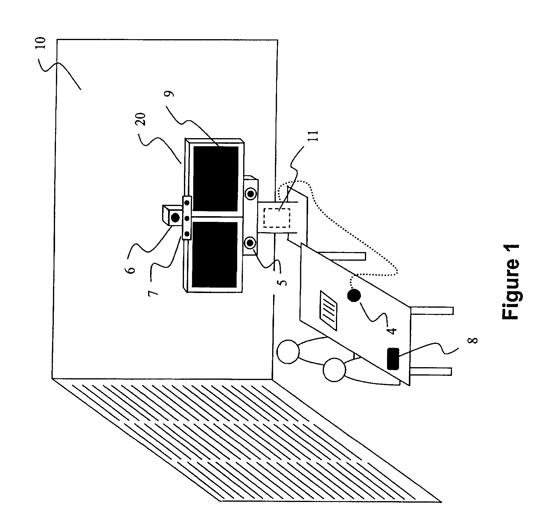
[0026]FIG. 1 illustrates a typical video conferencing room 10, with an exemplary video conferencing system 20. Video conferencing systems 20 may, for example, consist of the following comp...


PUM


Abstract

A method for automatically determining an orientation and zoom of an image pickup device associated with a video conferencing system, wherein the method includes the steps of: generating, at the image pickup device, an image signal representative of an image framed by the image pickup device; processing the image signal to identify objects plural users of the video conferencing system in the image; steering the image pickup device to an initial orientation; determining a location of all the identified objects relative to a reference point and determining respective sizes of the identified objects; defining an area of interest in the image, wherein the area of interest includes all the identified objects; and steering the image pickup device to frame the defined area of interest including all the identified objects where a center of the frame substantially coincides with a center of all the identified objects.

Description

CROSS-REFERENCE TO RELATED APPLICATIONS[0001]The present application claims the benefit of provisional application 60 / 949,718 under 35 U.S.C. §119, filed Jul. 13, 2007, which is incorporated herein by reference in its entirety. The present application claims the benefit of Norwegian application NO 20073621 under 35 U.S.C. §119, filed Jul. 13, 2007 in the Norwegian Patent Office, which is incorporated herein by reference in its entirety.FIELD OF THE INVENTION[0002]The present invention relates to automatic adjustment of camera orientation and zoom in situations, such as but not limited to, video conferencing.BACKGROUND OF THE INVENTION[0003]In most high end video conferencing systems, high quality cameras with pan-, tilt-, and zoom capabilities are used to frame a view of the meeting room and the participants in the conference. The cameras typically have a wide field-of-view (FOV), and high mechanical zooming capability. This allows for both good overview of a meeting room, and the p...

Claims


Application Information

Patent Timeline
Patent Type & Authority Patents(United States)
IPC IPC(8): H04N7/14
CPCH04N5/232H04N5/23219H04N5/23296H04N7/142H04N7/15H04N21/4223H04N21/4788H04N21/478H04N23/611H04N23/69
Inventor ENSTAD, GISLEKORNELIUSSEN, JAN TOREHUSOY, PER OVE
Owner CISCO TECH INC
Why Eureka
Try Eureka