LDPC check matrix generation method, check matrix generator, and code retransmission method

a technology of check matrix and generator, applied in the direction of coding, code conversion, instruments, etc., can solve the problems of complex processing, unoptimized codes obtained by applying puncturing,

Active Publication Date: 2012-05-01
FUJITSU LTD
View PDF20 Cites 21 Cited by
  • Summary
  • Abstract
  • Description
  • Claims
  • Application Information

AI Technical Summary

Benefits of technology

[0066]With the foregoing in view, it is an object of the present invention to provide an LDPC check matrix generation method and device which can generate check matrixes H0 and H1 having optimum weight distributions simultaneously for both the reference code C0 and code C1, where C0 and C1 are two LDPC systematic codes having encoding ratios R0 and R1 which are in a rate-compatible relationship, and a check matrix H1 of code C1 is generated from the check matrix H0 of the reference code C0.
[0067]It is another object of the present invention to provide an LDPC check matrix generation method and device which can generate the check matrix H1 of the code C1 from the check matrix H0 of the reference code C0 using a simple processing without requiring a large size memory.
[0068]It is still another object of the present invention to provide a retransmission control method which can characteristically optimize the codes obtained by puncturing in the retransmission control based on the IR method.

Problems solved by technology

With this conventional check matrix generation method, however, it is difficult to make the weight distributions of the check matrix H0 and check matrix H1 after extension to be the optimum simultaneously.
Also in the case of a conventional check matrix generation method, complicated processing is required to extend the check matrix, and a large size memory is required to hold the check matrix.
In the case of the retransmission control based on the IR method, puncturing is performed, but in the conventional check matrix generation method, codes obtained by applying puncturing are characteristically not the optimum.

Method used


Image

  • LDPC check matrix generation method, check matrix generator, and code retransmission method
  • LDPC check matrix generation method, check matrix generator, and code retransmission method
  • LDPC check matrix generation method, check matrix generator, and code retransmission method

Examples


first embodiment

[0106](A) First Embodiment

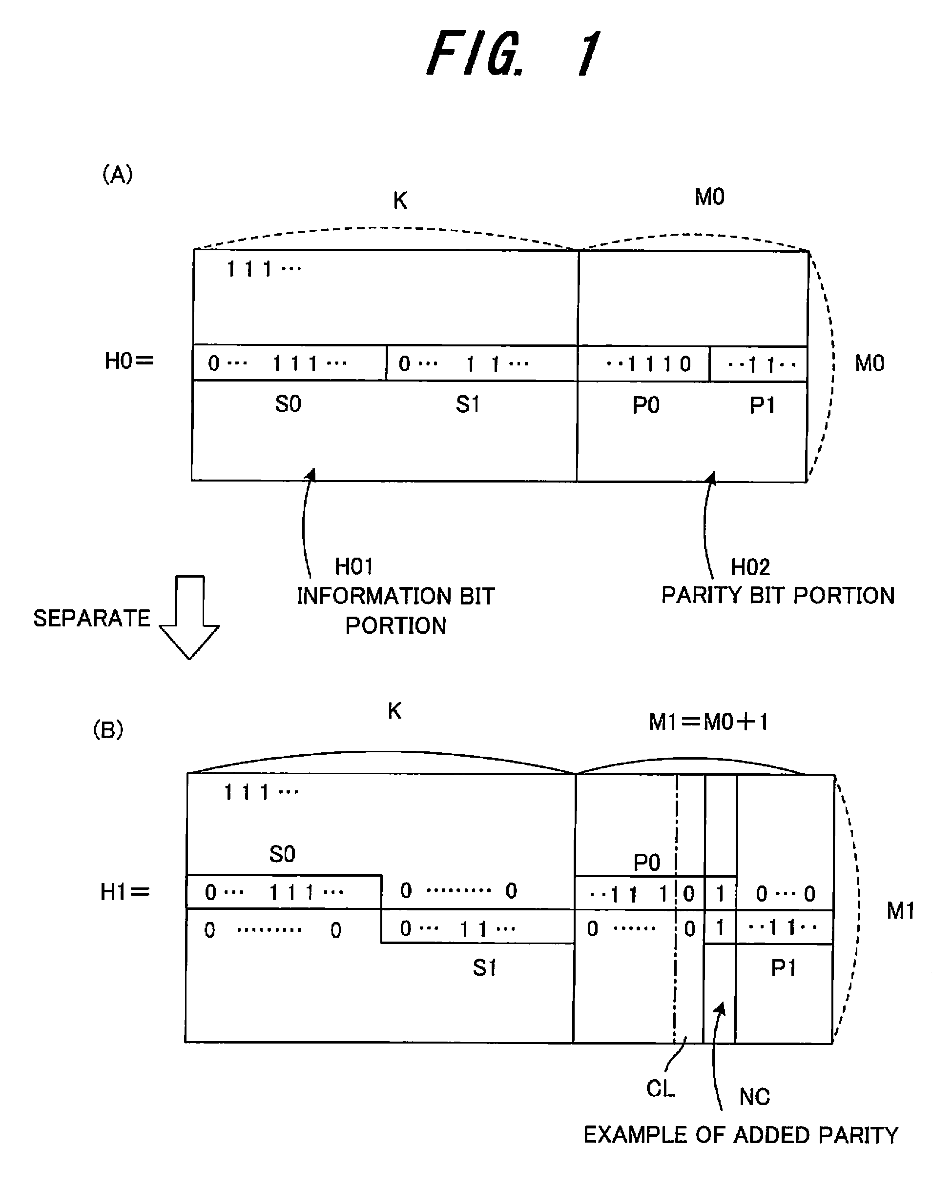
[0107]FIG. 1 is a diagram depicting a check matrix generation method according to the first embodiment.

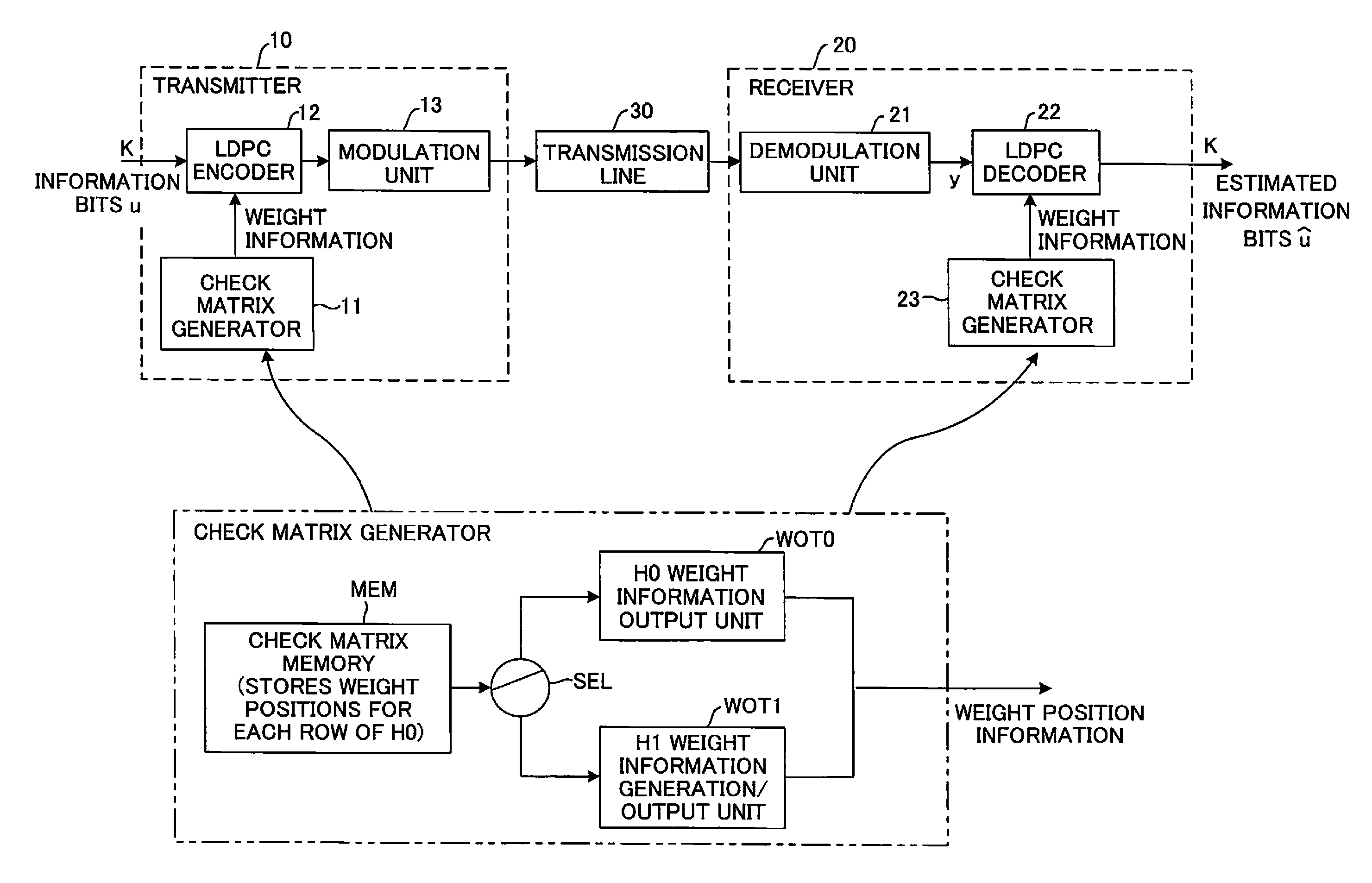
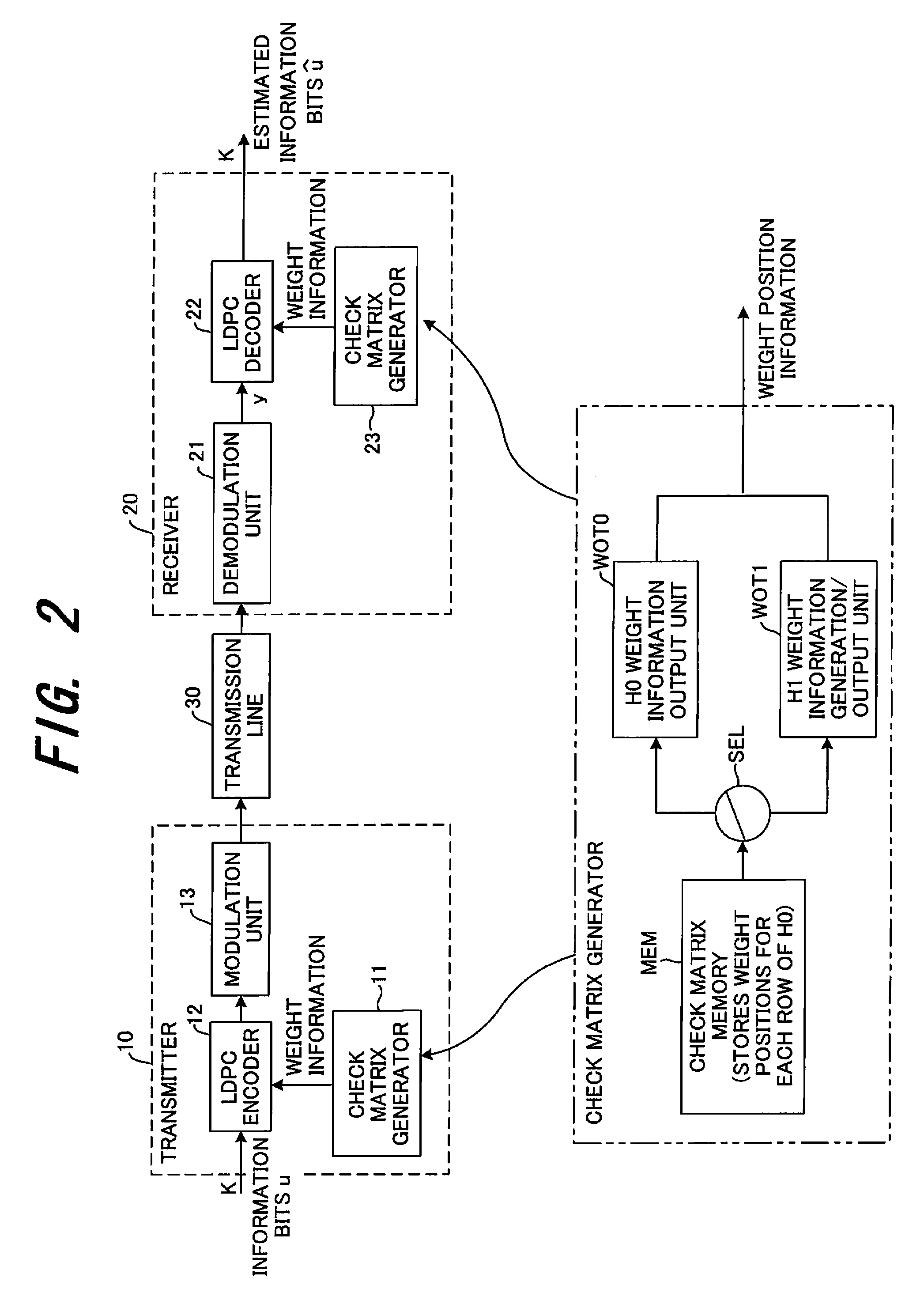
[0108]In a system for transmitting / receiving information bits, a transmitter is provided with a function for generating two LDPC codes C0 and C1 (see FIG. 21) having different encoding ratios which are in a rate-compatible relationship and transmitting these codes, and a receiver is provided with a function for receiving the two LDPC codes C0 and C1 having different encoding ratios and decoding these codes.

[0109]The LDPC codes C0 and C1 are both systematic codes, and the information bit sizes thereof are K and parity sizes thereof are M0 and M1=M0+1 respectively. The parity bits of the code C1 are created by adding one parity bit to the parity bits of the code C0. Weight distribution of a check matrix H0 of the code C0 is optimized so that a irregular LDPC code can be generated.

[0110]In this case, a check matrix H1 of the code C1 is generated from the chec...

second embodiment

[0128](B) Second Embodiment

[0129]FIG. 3 is a diagram depicting a check matrix generation method according to the second embodiment.

[0130]In a system for transmitting / receiving information bits, a transmitter is provided with a function for encoding information bits into two rate-compatible IRA codes C0 and C1 (see FIG. 21) having different encoding ratios, and transmitting these codes, and a receiver is provided with a function for receiving the two LDPC codes C0 and C1 having different encoding ratios, and decoding these codes. The IRA codes C0 and C1 are LDPC codes, and are both systematic codes, and the information bit sizes thereof are K and parity sizes thereof are M0 and M1 respectively, and code bit sizes are N0 and N1 respectively. Here N0=K+M0, N1=K+M1 and M1=2×M0. A parity bit portion H02 of the check matrix H0 of the IRA code C0 is in a step type matrix, where the weight number of the column is 2 except for last column, as shown in (A) of FIG. 3. In this case, the check m...

third embodiment

[0152](C) Third Embodiment

[0153]The second embodiment can be extended to cyclic matrix type IRA codes. In a system for transmitting / receiving information bits, a transmitter is provided with a function for encoding information bits into two IRA codes, C0 and C1, having different encoding ratios and transmitting these codes, and a receiver is provided with a function for receiving the two LDPC codes C0 and C1 (see FIG. 21) having different encoding ratios, and decoding these codes. The information bit sizes of the codes C0 and C1 are K, parity sizes thereof are M0 and M1 respectively, and code bit sizes are N0 and N1 respectively. Here N0=K+M0, N1=K+M1, and M1=2·M0. It is assumed that the size of the cyclic matrix is z×z, and that M0, M1 and K are exactly divisible by z, and m0=M0 / z, m1=M1 / z and k=K / z.

[0154]FIG. 5 is a diagram depicting a method for generating the check matrix H1 of the cyclic matrix type IRA code C1 from the check matrix H0 of the cyclic matrix type IRA code C0. The...


PUM


Abstract

A check matrix generation method for generating a check matrix H1 of a code H1 from a check matrix H0 of a code C0, where codes C0 and C1 are LDPC systematic codes having different encoding ratios in a rate-compatible relationship and information bit sizes of the systematic codes C0 and C1 are K, and parity bit sizes thereof are M0 and M1 (M1−M0=L) respectively. The method comprising steps of: selecting L number of rows out of the check matrix H0; separating an information bit portion and a parity bit portion constituting each of the selected rows into two respectively, such that each of the separated information bit portions includes one or more non-zero elements which are “elements different from 0”; creating a new first row by coupling one separated information bit porting and one separated parity bit portion and creating a new second row by coupling another separated information bit portion and another separated parity portion; and generating the check matrix H1 of the systematic code C1 by placing the new first and second rows in place of each of the selected L number of rows in the check matrix H0.

Description

CROSS REFERENCE TO RELATED APPLICATION[0001]This application is continuation of PCT Application no. PCT / JP2006 / 302246 filed on Feb. 9, 2006, pending the entire contents of which are incorporated herein by reference.BACKGROUND OF THE INVENTION[0002]The present invention relates to an LDPC check matrix generation method, check matrix generator, and code retransmission method, and more particularly to an LDPC check matrix generation method, check matrix generator and code retransmission method, by which when two LDPC systematic codes having different encoding ratio in a rate-compatible relationship are C0 and C1, and the information bit sizes of the codes C0 and C1 are both K, and the parity bit sizes thereof are M0 and M1 (M0<M1) respectively, the check matrix H1 or H0 of one code, C1 or C0, is generated from the check matrix H0 or H1 of the other code C0 or C1.[0003]Systematic Code and Block Code[0004]In general, encoding using an information alphabets having q number of different...

Claims


Application Information

Patent Timeline
Patent Type & Authority Patents(United States)
IPC IPC(8): G06F11/00
CPCH03M13/116H03M13/1168H03M13/1185H03M13/1188H03M13/6306H03M13/6393H04L1/0057H04L1/1819H03M13/09
Inventor MIYAZAKI, SHUNJI
Owner FUJITSU LTD
Why Eureka
Try Eureka