Nozzle and/or adaptor unit on cartridge

a technology of adaptor unit and cartridge, which is applied in the direction of container, liquid/fluent solid measurement, volume measurement, etc., can solve the problems of cartridge contents contaminating user's clothing, contaminating fingers with the leaked contents of the cartridge, and preventing any possible piercing of the cartridge. , the effect of preventing the hardening of mixed materials

Active Publication Date: 2012-05-08
THE RAWLPLUG CO INC
View PDF26 Cites 7 Cited by
  • Summary
  • Abstract
  • Description
  • Claims
  • Application Information

AI Technical Summary

Benefits of technology

[0023]Typically, the outer casing may be adapted to receive the cartridge and form a snug fit with the outer walls of the cartridge. The snug fit may help to prevent radial expansion (i.e. widening) on application of pressure to an end of the cartridge.
[0025]Conveniently, the dispensing apparatus may comprise an expansion chamber into which the cartridge may partially expand into on application of pressure to an end of the cartridge. The expansion chamber may be substantially funnel-like in shape and contains no sharp edges which may cut the film forming the cartridge. The apparatus may be adapted so that on application of pressure to one end of the cartridge, expansion in the axial direction is prevented so that at the opposite end to which the pressure is applied, the cartridge deforms into an initial bulbous confirmation and may partially fill the expansion chamber.
[0027]In an alternative embodiment, the reaction shoulder may be formed with a separate insert which may be inserted into the outer casing. In a yet further alternative, the cartridge may be glued to the side of the outer casing thereby preventing movement along the length of the outer casing.
[0029]Conveniently, the dispensing apparatus comprises a nozzle member which may be fitted to an end of the outer casing via, for example, a screw thread. The nozzle may comprise an integral mixer unit which further aids the mixing of the different products in the flexible cartridge. Alternatively, the mixer unit may be a separate item and may be inserted into the nozzle. Preferably, the diameter of the nozzle is wide enough to prevent blockage on release of the sealing means.
[0031]Preferably, the sealing means may be formed from any metal or plastics material such as soft aluminium or steel wire which is wound round the ends of the cartridge. The sealing means is not attached too tightly or too strongly as this will prevent the release of the sealing means on application of pressure to the cartridge. It is also preferred that any sharp ends formed by the sealing means may be pointed away from the flexible cartridge thereby preventing any possible piercing of the cartridge.
[0032]Preferably, the film forming the cartridge may be adapted so that on expansion into the expansion chamber, the film extends part way into the expansion chamber. This may prevent mixing of different compounds and may therefore prevent any hardening of mixed materials within the apparatus. This may allow the apparatus to be used at a later date without completely emptying the contents of the cartridge. Typically, the apparatus may be used to provide dispensed products for use in chemical anchors, sealants, food processing and medical applications. Uses of chemical anchors includes securing bolts in concrete / masonry, forming a stud socket and post-installed rebar connections.

Problems solved by technology

However, it is found that cartridges during storage may sometimes have some form of leakage.
A user therefore removing the cartridge from any form of packaging or inserting the cartridge into a dispensing gun may contaminate their fingers with the leaked contents of the cartridge.
The contents of the cartridge may also contaminate clothing of a user.

Method used


Image

  • Nozzle and/or adaptor unit on cartridge
  • Nozzle and/or adaptor unit on cartridge
  • Nozzle and/or adaptor unit on cartridge

Examples


Embodiment Construction

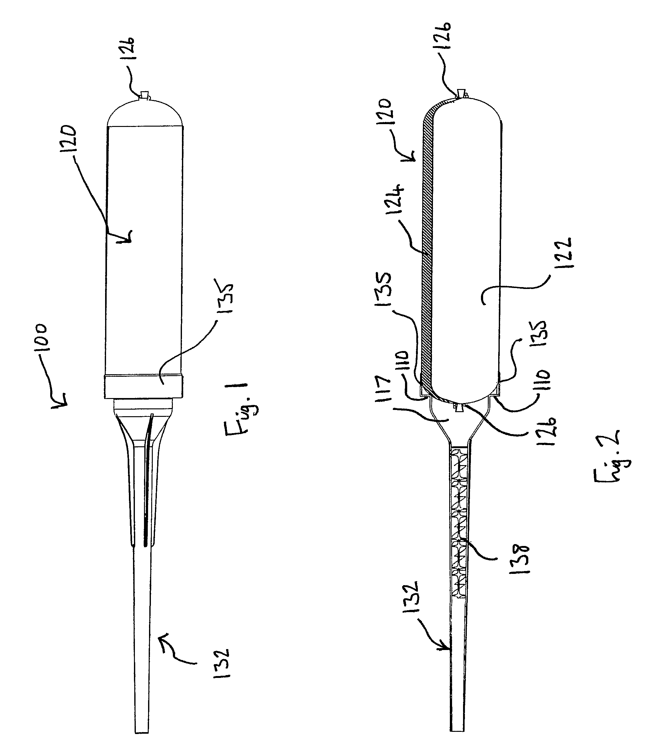
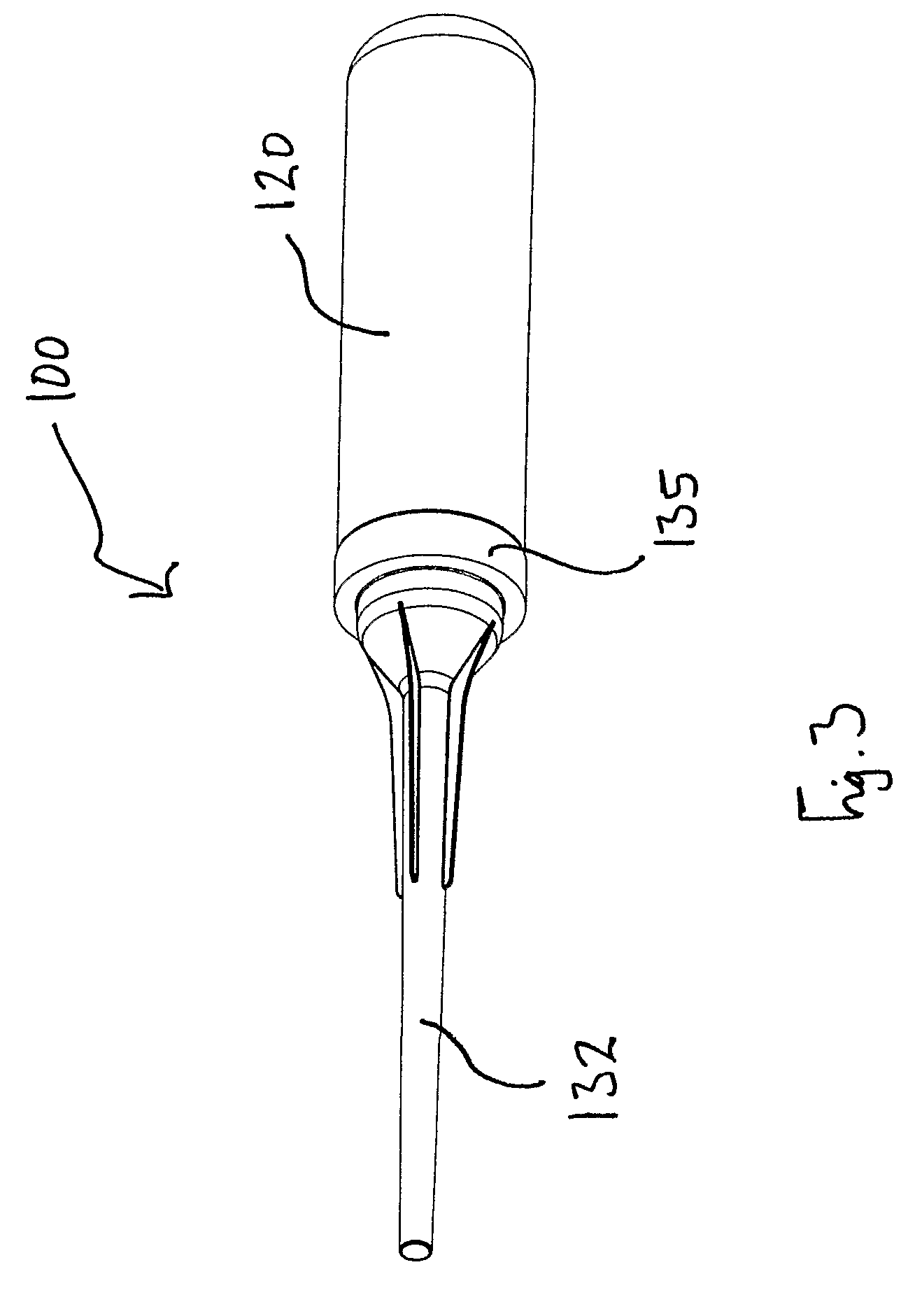
[0050]Referring to FIG. 1, there is dispensing apparatus, generally designated 100. The dispensing apparatus 100 comprises a cartridge 120 which is attached to a nozzle 132. Part of an annular portion 135 of the nozzle 132 is securely attached to the cartridge 120.

[0051]FIG. 2 is a sectional view of the dispensing apparatus 100. As shown in FIG. 2, the nozzle 132 is attached using part of the annular portion 135 which extends around an end of the cartridge 120. The nozzle 132 is attached to the cartridge 120 by applying adhesive to the inner surface of the annular portion 135 and is then slid onto the cartridge 120. About 5 mm of the annular portion 135 is secured to the cartridge 120. By attaching the nozzle 132 in this manner, helps to contain any leakage seeping from sealing means 126 on the cartridge 120.

[0052]The cartridge 120 is a two-component cartridge containing a first component 122 and a second component 124. As shown in FIG. 2, the cartridge is abutting against shoulders...


PUM


Abstract

A cartridge (120) secured to either a nozzle (110) and / or adaptor unit wherein the nozzle or adaptor unit comprises a substantially annular portion (135) adapted to fit snugly around an end of the cartridge (120) wherein the substantially annular portion (135) acts as a seal against any leakage from the cartridge (120).

Description

CROSS-REFERENCE TO RELATED APPLICATIONS[0001]This application claims priority under the provisions of 35 USC §371 of International Application No. PCT / GB07 / 00439 filed Feb. 7, 2007, which in turn claims priority of United Kingdom Patent Application No. 0602340.2 filed Feb. 7, 2006. The disclosures of such international application and United Kingdom priority application are hereby incorporated herein by reference in their respective entireties, for all purposes.FIELD OF THE INVENTION[0002]The present invention relates to a cartridge unit suitable for storing and dispensing of products. In particular, the present invention relates to a cartridge containing an integral nozzle and / or adaptor unit.BACKGROUND OF THE INVENTION[0003]Dispensing apparatus in the form of cartridges is well-known in the art. In many instances, it is necessary to mix at least two different compounds together. On mixing, the compounds may react and usually harden. This type of technology is commonly used in chem...

Claims


Application Information

Patent Timeline
Patent Type & Authority Patents(United States)
IPC IPC(8): B65D35/22B67D7/78
CPCB05C17/00513B05C17/00506B65D83/0072B05C17/00583B05C17/00596
Inventor CADDEN, STEPHEN
Owner THE RAWLPLUG CO INC
Why Eureka
Try Eureka