Axial load bearing assembly

a technology of axial load bearings and bearings, which is applied in the direction of bearings, shock absorbers, transportation and packaging, etc., can solve the problems of limited ability of conventional bearing isolators and lack of tuning ability of bearing isolators

Active Publication Date: 2016-12-22
STEERING SOLUTIONS IP HLDG
View PDF2 Cites 0 Cited by
  • Summary
  • Abstract
  • Description
  • Claims
  • Application Information

AI Technical Summary

Benefits of technology

[0005]In one exemplary embodiment of the present disclosure, an axial load bearing assembly that may be for a steering gear box apparatus includes a first member, a second member, a jacket, and an elastomeric ring. The first member includes a first surface facing axially with respect to a centerline. The second member is constructed and arranged to move axially with respect to the first member between an extended state and a compressed state. The second member includes a second surface that axially opposes the first surface. The jacket is engaged to one of the first and second members, and includes a face facing radially inward. The elastomeric ring is disposed axially between the first and second members for axial compression, and is in biased contact with the face at least when in the compressed state preventing radial expansion of the elastomeric ring during axial compression.

Problems solved by technology

Unfortunately, such conventional bearing isolators may be limited in their ability to provide sufficient range of travel together with desirable force characteristics.
Such bearing isolators may also lack the ability to be tuned so as to provide desirable force characteristics through necessary ranges of travel along the worm axis.

Method used


Image

  • Axial load bearing assembly
  • Axial load bearing assembly
  • Axial load bearing assembly

Examples


Embodiment Construction

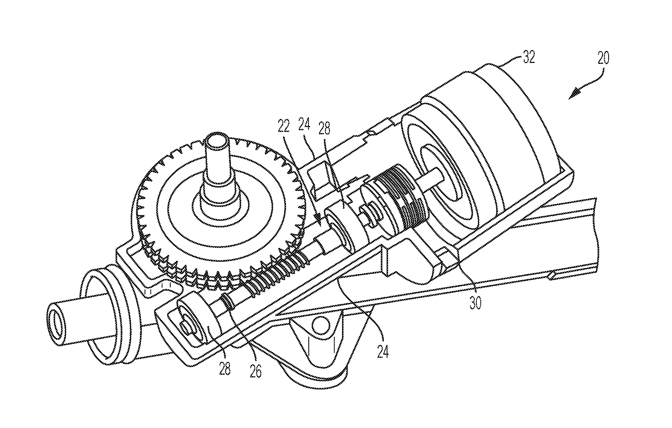
[0020]Referring now to the Figures, where the invention will be described with reference to specific embodiments, without limiting same, an electric power steering gear box apparatus 20 is illustrated as one, non-limiting, application of an axial bumper device 22 that may be a bearing isolator device. Although not illustrated, the gear box apparatus 20 may be applied to a single pinion electric power steering system or a column electric power steering system as is known in the art. The steering gear box apparatus 20 may include the bearing isolator device 22, an outer casing 24, a worm gear shaft 26, and a bearing 28 (two illustrated) for rotatably supporting the worm gear shaft 26. The bearings 28 may be engaged to the casing 24 and allow for limited axial movement of the worm gear shaft 26 relative to the casing 24 and the bearings 28. A rotating motor shaft 30 of the gear box apparatus 20 is connected axially between the worm gear shaft 26 and an electric motor 32 of the gear box...


PUM

PropertyMeasurementUnit
forceaaaaaaaaaa
forceaaaaaaaaaa
forceaaaaaaaaaa

Abstract

An axial load bearing assembly that may be for a steering gear box apparatus includes a first member, a second member, a jacket, and an elastomeric ring. The first member includes a first surface facing axially with respect to a centerline. The second member is constructed and arranged to move axially with respect to the first member between an extended state and a compressed state. The second member includes a second surface that axially opposes the first surface. The jacket is engaged to one of the first and second members, and includes a face facing radially inward. The elastomeric ring is disposed axially between the first and second members for axial compression, and is in biased contact with the face at least when in the compressed state preventing radial expansion of the elastomeric ring during axial compression.

Description

CROSS-REFERENCE TO RELATED APPLICATION[0001]This patent application claims priority to U.S. Provisional Patent Application Ser. No. 62 / 182,111, filed Jun. 19, 2015 which is incorporated herein by reference in its entirety.BACKGROUND OF THE INVENTION[0002]The present disclosure relates to axial load bearing assemblies, and more particularly, to an axial load bearing assembly that includes a resilient ring providing a plurality of force characteristics along an axial range of travel.[0003]Existing axial load bearing assemblies such as bearing isolator assemblies seek to absorb manufacturing tolerances of associated components, pre-load bearings with axial loads to eliminate looseness and unwanted bearing noise, and control worm travel and rate of deceleration. Absorption of manufacturing tolerances of worm and bearing assemblies may be accomplished while limiting travel of the components by modulating a quantity of elastomer disposed within a pair of steel cups such that the elastomer...

Claims


Application Information

Patent Timeline
Patent Type & Authority Applications(United States)
IPC IPC(8): B62D5/04F16C39/02F16H1/16F16C25/08
CPCB62D5/0403F16C25/083F16C39/02B62D3/04B62D5/0454F16C2361/65F16C2240/14F16H1/16B62D3/10B62D5/0409B62D5/0421F16F1/376F16F1/3732F16F2224/025
Inventor SUNDHOLM, BRAD S.RUTKIEWICZ, JASONVON MATT, NIKBEYERLEIN, ROBERT E.
Owner STEERING SOLUTIONS IP HLDG
Why Eureka
Try Eureka