
Stamped cover for clutch system

A technology of a clutch device and a cover plate, applied in the field of clutch systems, can solve the problems such as the expansion of the rotating ring and the radial outward movement of the rotating element.

Pending Publication Date: 2021-10-08
SCHAEFFLER TECH AG & CO KG
View PDF18 Cites 0 Cited by
  • Summary
  • Abstract
  • Description
  • Claims
  • Application Information

AI Technical Summary

Problems solved by technology

In addition, as the shaft rotates, centrifugal force may cause the rotating element to move radially outward and cause the rotating ring to expand radially outward

Method used


Image

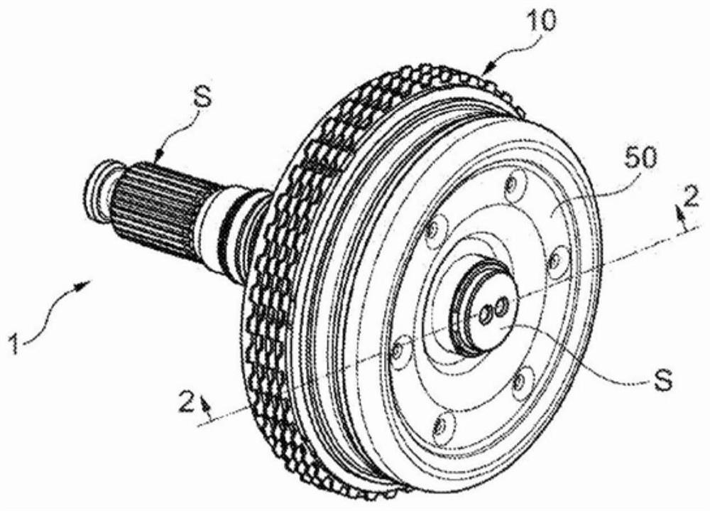
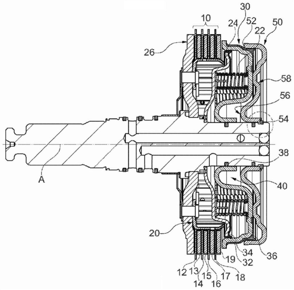
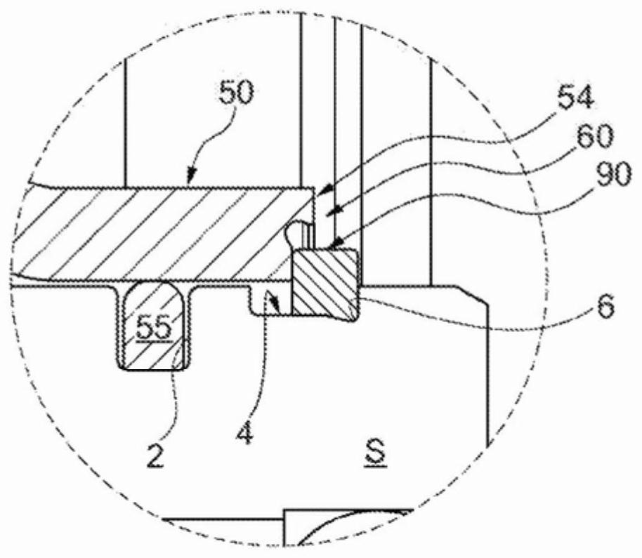
  • Stamped cover for clutch system
  • Stamped cover for clutch system
  • Stamped cover for clutch system

Examples


Embodiment Construction

[0016] The present disclosure relates to a retaining feature of a cover plate of a clutch assembly for retaining a retaining ring. The retention features and retention rings are specifically designed for the purposes discussed herein.

[0017] At the outset, it should be understood that like reference numerals appearing in different drawings identify identical or functionally similar structural elements. Furthermore, it is to be understood that this disclosure is not limited to the particular embodiments, methods, materials and modifications described herein, as such may, of course, vary. It is also to be understood that the terminology used herein is for the purpose of describing particular aspects only and is not intended to limit the scope of the present disclosure which will be limited only by the appended claims.

[0018] Unless defined otherwise, all technical and scientific terms used herein have the same meaning as commonly understood by one of ordinary skill in the a...


PUM

PropertyMeasurementUnit
Lengthaaaaaaaaaa

Abstract

A cover for a clutch system with a hydraulic piston is axially retained by a retaining ring. The cover has a retaining feature to radially retain this retaining ring against centrifugal forces.

Description

[0001] Cross References to Related Applications [0002] This application claims the benefit of U.S. non-provisional application No. 16 / 299,696, filed March 12, 2019, the contents of which are incorporated herein by reference. technical field [0003] The present disclosure relates to clutch systems, and more particularly, to a cover plate for a clutch system having a retaining feature on the clutch plate to engage a retaining ring on a shaft. Background technique [0004] The present disclosure relates to a clutch system for a power train of a motor vehicle including a rotating shaft, such as a passenger car, truck, bus or utility vehicle, the clutch system comprising a clutch (friction clutch / friction coupling) and a clutch actuation A clutch system comprising a piston displaceable in an axial direction of a clutch device to engage and disengage a clutch disc of a clutch pack with a crankshaft of an internal combustion engine. A hydraulically displaceable actuating piston...

Claims


Application Information

Patent Timeline
IPC IPC(8): F16D25/0638F16D25/10F16D25/12
CPCF16D25/0638F16D25/12F16D2300/12F16D13/58
Inventor 亚历山大·孔
Owner SCHAEFFLER TECH AG & CO KG
Learn More