
Covering and component parts thereof

a technology of components and covers, applied in the field of covers, can solve the problems of relatively difficult mounting, difficult assembly of various components in situ, and suffer from the covers such as described abov

Inactive Publication Date: 2013-02-14
HUNTER DOUGLAS IND BV
View PDF19 Cites 0 Cited by
  • Summary
  • Abstract
  • Description
  • Claims
  • Application Information

AI Technical Summary

Benefits of technology

The patent allows for a covering to expand in a way that avoids the need for a larger space during deployment, allowing for a smaller roller and housing. It also suggests using a roller in each end rail to make the covering more flexible and easier to position. Overall, the patent improves the size and flexibility of coverings for architectural openings.

Problems solved by technology

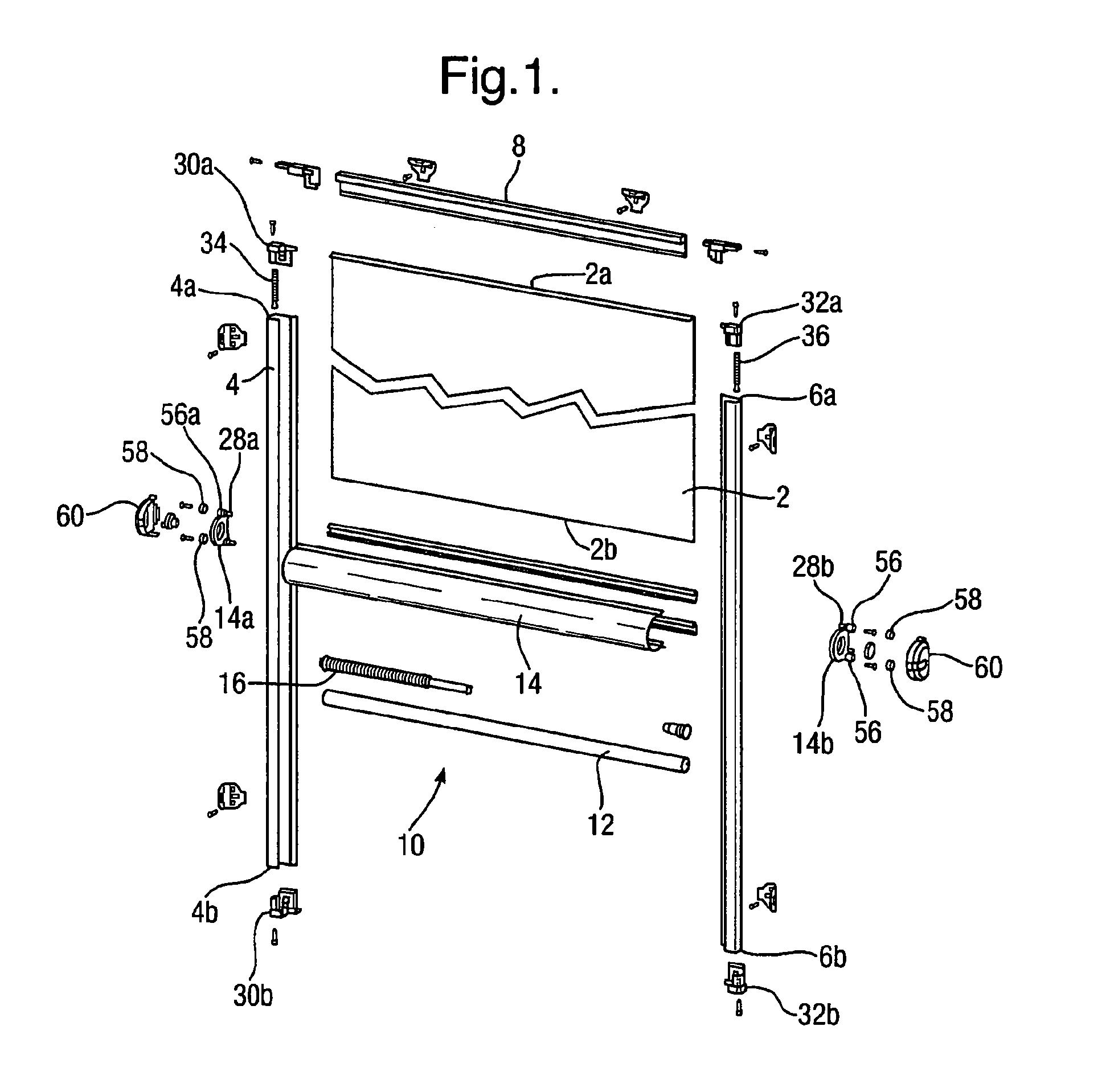
In general, coverings such as described above suffer from the problem that they are relatively difficult to mount.
Also, assembly of the various components in situ can be somewhat complicated, requiring precise measurement and positioning of the various components.

Method used


Image

  • Covering and component parts thereof
  • Covering and component parts thereof
  • Covering and component parts thereof

Examples


first embodiment

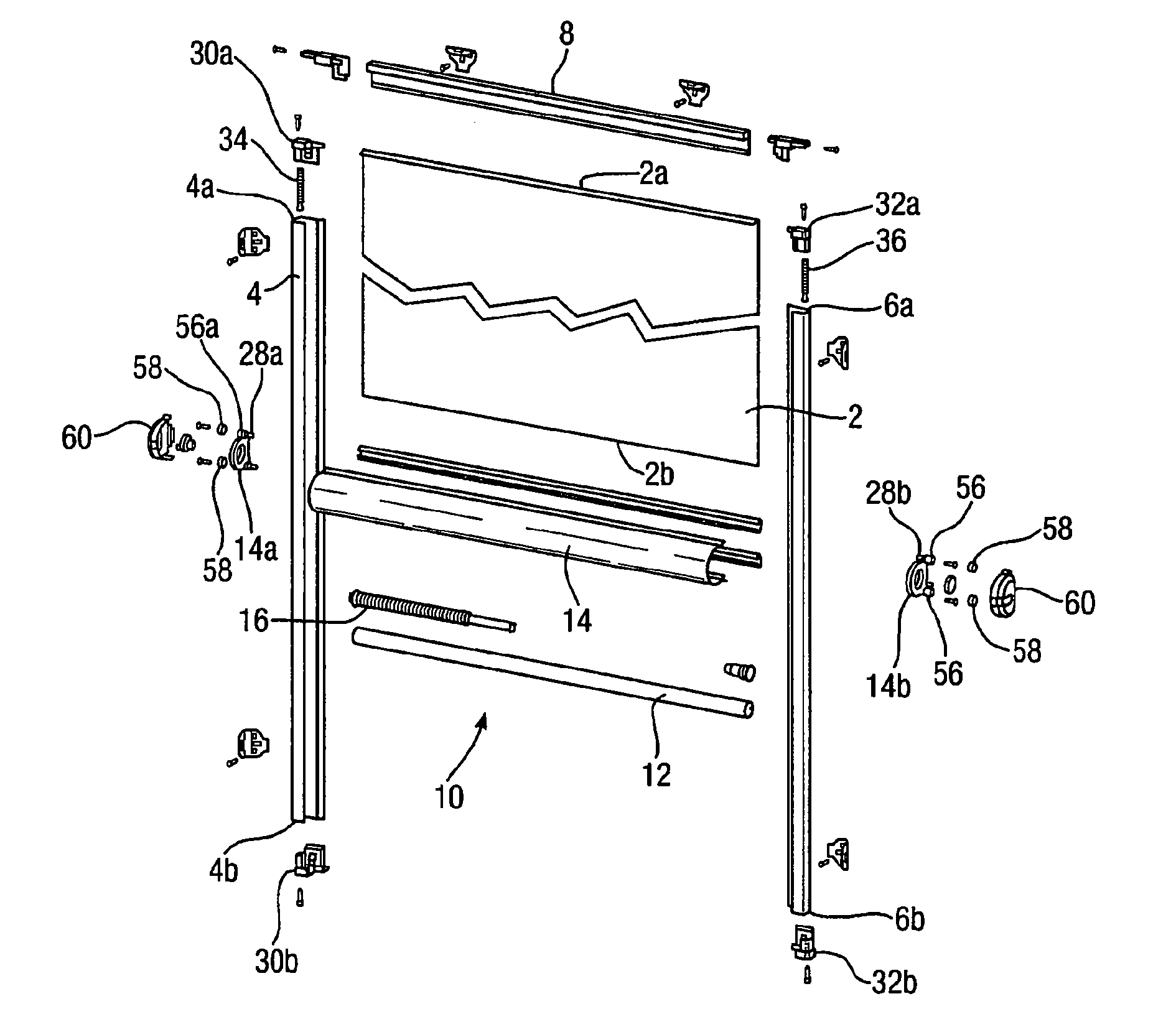
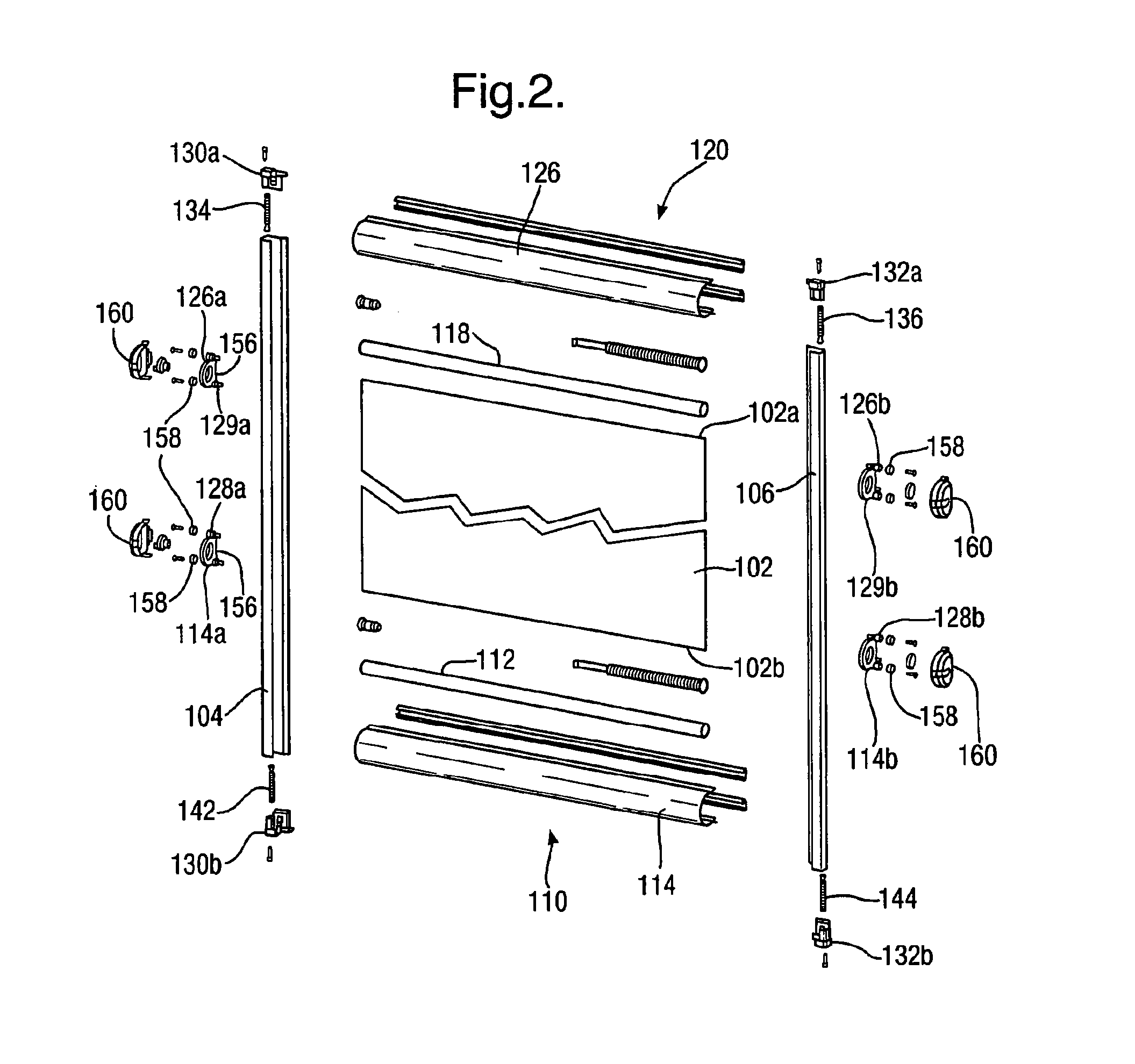
[0111]The ends of the cords 122, 124 can be secured to the left and right side rails 104, 106 at their respective top end caps 130a, 132a by means of small coil springs 134 and 136 respectively. The end of the cord is attached to the coil spring, routed through the coil spring and about the end cap to run downwardly parallel to the coil spring and continue the routing as described above. The coil springs 134, 136 provide tension to the cords 122, 124 which provides the right amount of frictional resistance to movement the movable end rail 110 and arranges the abovementioned stable and secure positioning for the movable rail 110. Furthermore, compression of the coil springs 134, 136 allows assembly to be changed from a usable configuration with the movable rails 110, 120 perpendicular relative to the orientation of the left and right side rails 104, 106 to an orientation in which all rails (movable rails and side guide rails) are parallel to each other. This is particularly useful fo...

second embodiment

[0112]Each movable rail of the second embodiment is provided with a tension cord arrangement for stable and secure positioning thereof. The left and right housing ends 126a, 126b of the upper housing 126 of the upper movable rail 120 illustrated in FIG. 3(a) is threaded with their own pair of cords 138, 140 (not illustrated in this Figure). The cord routing of these cords 138, 140 is in the reverse pattern to the first pair of cords 122,124 for the lower movable rail 110. In other words the ends of these third and fourth cords 138, 140 can be secured to the left and right side rails 104, 106 at their respective bottom end caps 130b, 132b by means of small coil springs 142 and 144 respectively. The end of the cord is attached to the coil spring, routed through the coil spring and about the end cap to run upwardly parallel to the coil spring and continue the routing. For the third cord 138 this means that the cord is routed up along the left side guide 104, to housing end 126a of the...


PUM


Abstract

An architectural covering arrangement having two side rails for mounting in parallel either side of a window pane and at least one movable end rail for mounting perpendicular to the side rails and extending from one side rail to the other side rail, the side rails having on respective faces to be mounted on a window pane, a two-layer fastening structure with one of the layers adhered to the respective side rail and the other of the two layers to be adhered to the window pane, the two layers being freely attachable and detachable from one another.

Description

CROSS REFERENCE TO RELATED APPLICATIONS[0001]This application is continuation of co-pending U.S. patent application Ser. No. 12 / 302,102 filed on Dec. 12, 2008, now U.S. Pat. No. 8,205,657 and entitled “Covering and Component Parts Thereof”, which is a national stage application of PCT Patent Application No. PCT / EP2007 / 005081 filed on Jun. 8, 2007 and entitled “Covering and Component Parts Thereof”, which claims priority to European Patent Application No. 06252982.1 filed on Jun. 9, 2006 and entitled “Covering and Component Parts Thereof” which applications are hereby incorporated by reference into the present application in their entireties.BACKGROUND OF THE INVENTION[0002]A wide range of coverings for architectural openings have been proposed in the past, including blinds to reduce or substantially eliminate light passing through the architectural opening, fly screens and the like. The arrangement of the covering material has been proposed in many different forms, for example a fla...

Claims


Application Information

Patent Timeline
Patent Type & Authority Applications(United States)
IPC IPC(8): E06B9/58
CPCE06B9/58E06B9/42E05Y2201/688E05Y2201/684
Inventor BOHLEN, JORG
Owner HUNTER DOUGLAS IND BV
Learn More