Ligation clip applier

a clip and applicator technology, applied in the field of mechanical devices, can solve the problems of ligation clips, variable force applied by the clip to the vessel, and difficulty in removal or repositioning,

Active Publication Date: 2012-05-08
MICROLINE SURGICAL INC
View PDF221 Cites 385 Cited by
  • Summary
  • Abstract
  • Description
  • Claims
  • Application Information

AI Technical Summary

Problems solved by technology

Such crushing actions, of course, permanently deform the clips, making them difficult to remove or re-position.
Prior art surgical ligation clips have several inherent problems.
For example, the force applied by the clip to the vessel can be variable and inconsistent from one clip to the next, because of the variation in crushing force applied to the clip by the user.
Further, prior art clips have a tendency to slip off the end of the blood vessel stub (i.e., perpendicular to the axis of the vessel) to which it has been applied, because of the low coefficient of friction associated with the clip, and lack of adequate restraining force provided by the clip.
A related problem found in the prior art is the fact that the ligating or restraining force offered by the crushed clip varies along the length of the clip, decreasing toward the open end.
Thus, the section of the vessel near the open end of the clip can be inadequately ligated.
This does not lend itself to clip applier designs that will pass through small 5 mm trocars.
Unfortunately, several problems are encountered in applying the spring-action ligation clip of U.S. Pat. No. 5,593,414 to a vessel through a 5 mm or smaller trocar port.
First, the nominal 5 mm cross-section of the clip that is inserted through the trocar places severe design restrictions on any applier mechanism.
Secondly, these spring clips are small and compact and owing to the preload, have a great deal of energy stored in the spring.
This energy makes controlling the clip, to insure proper installation, difficult.
Undesirable translation or rotation can result in misplacement or dropping of the clip inside the body.
Fogelberg et al. still struggles with the complex manipulation required to advance the clip in a closed position and then open the clip prior to placement.
There are several problems associated with the spring clip applicators of the prior art.
This creates a severe pinching force on tissue that might be located near the axis or pivot point.
This pinching force can cause a hematoma or otherwise damage the tissue.
Secondly, the diverging surfaces of the jaws often obstruct the surgeon's view of the tissue to be ligated owing to the acute angle of the laparoscopic camera and the clip applier.

Method used


Image

  • Ligation clip applier
  • Ligation clip applier
  • Ligation clip applier

Examples


Embodiment Construction

[0035]Reference will now be made in detail to the present preferred embodiments (exemplary embodiments) of the invention, examples of which are illustrated in the accompanying drawings.

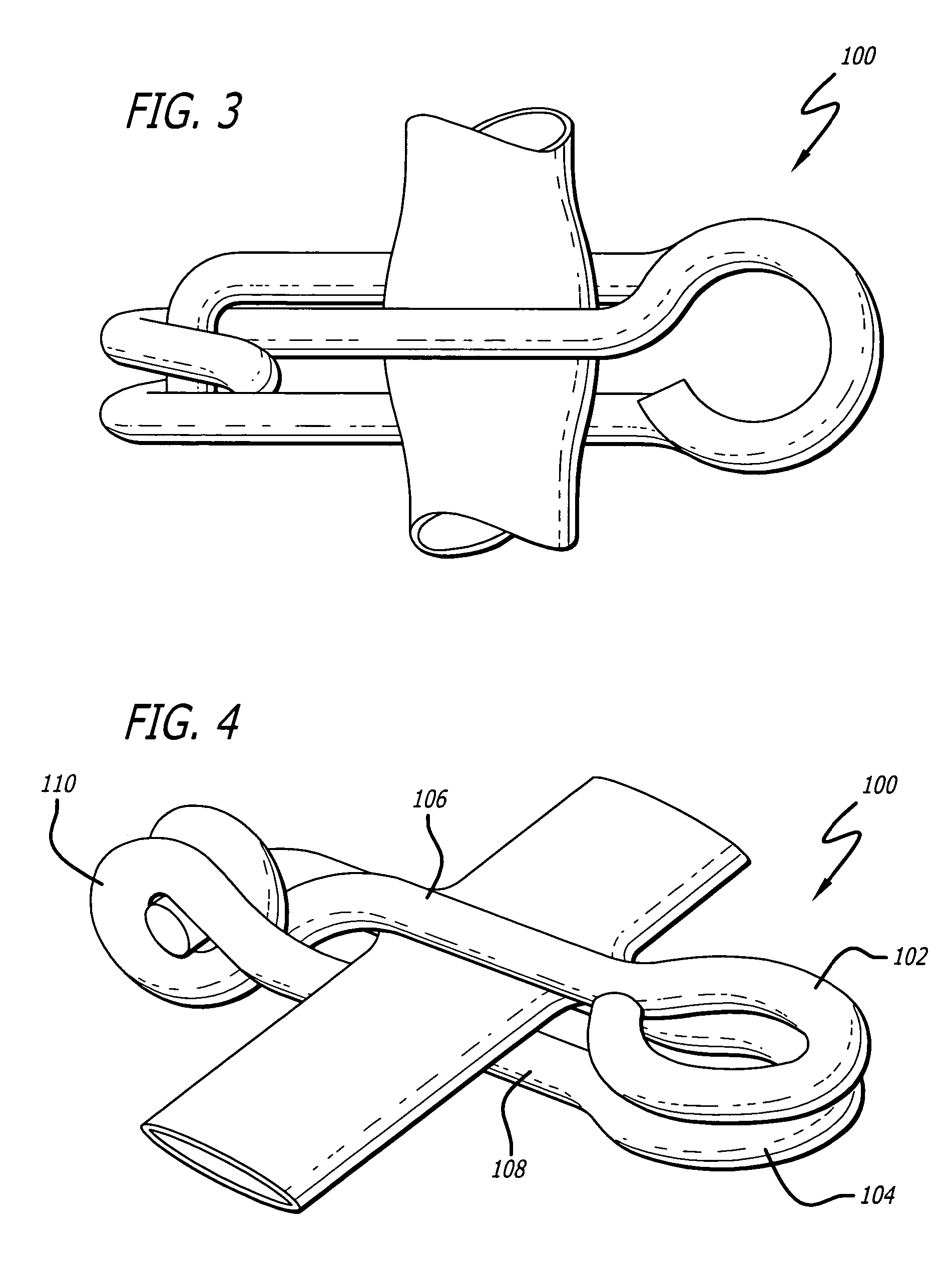
[0036]FIGS. 3 and 4 show an example of a surgical ligation clip 100 usable with a preferred embodiment of the clip applier of the present invention. Surgical ligation clip 100 includes a clamping arm 106 and a support member 108. A coil tension spring 110, which may also be generally referred to as a connector, joins clamping arm106 and support member 108.

[0037]Clamping arm 106 has a first enlarged end 102 defined thereon. Support member 108 has a second enlarged end 104 defined thereon. The first and second enlarged ends 102, 104 are first and second wire loops which are integrally formed with clamping arm 106 and support member 108 of clip 100.

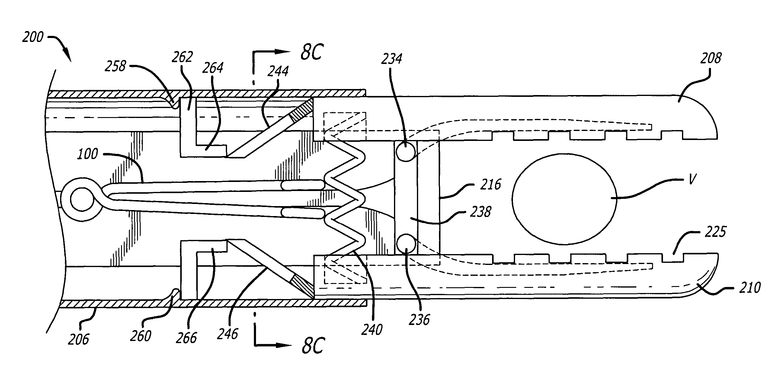
[0038]Loops 102, 104, and particularly the laterally outer portions thereof, may be described as first and second control surfaces being received in and trapp...


PUM


Abstract

A ligation clip applicator design is provided that is particularly applicable to placement of a surgical ligation clip during a laparoscopic surgical procedure. The applicator has a magazine including first and second longitudinally extending partially closed channels within which enlarged portions of a ligation clip are received and held in an open position. First and second substantially parallel compression members are attached to the magazine and have first and second channel extensions therein aligned with the first and second channels of the magazine for receiving the first and second enlarged portions of the clip. The channel extensions include first and second releasing openings. The compression members close about a vessel, remaining substantially parallel as they close. The clip is pushed forward into the compression members to a position where the enlarged portions of the clip are aligned with the releasing openings, permitting the clip to be released to close and ligate the vessel.

Description

[0001]The present application claims the benefit of U.S. provisional Application No. 60 / 477,106, filed Jun. 9, 2003, and U.S. provisional Application No. 60 / 513,518, filed Oct. 21, 2003, the disclosures of which are incorporated herein by reference.BACKGROUND OF THE INVENTION[0002]1. Field of the Invention[0003]The present invention relates generally to mechanical devices used in surgical procedures to obtain ligation or hemostasis, and more particularly, to low profile tools that can apply a pre-formed, spring loaded ligation clip used during surgery to clamp around a vessel or duct, such as the cystic duct, and thereby obtain ligation.[0004]2. Description of the Prior Art[0005]It will be appreciated by those skilled in the art that the use of ligation clips to control bleeding during surgical procedures is well known. As described, for example, in U.S. Pat. Nos. 4,976,722 and 4,979,950, prior art clips are generally formed of metal wire, usually a titanium alloy, having a “U-shape...

Claims


Application Information

Patent Timeline
Patent Type & Authority Patents(United States)
IPC IPC(8): A61B17/00A61B17/08A61B17/122A61B17/128
CPCA61B17/1285A61B17/083A61B17/1227
Inventor SHIPP, JOHN I.
Owner MICROLINE SURGICAL INC
Why Eureka
Try Eureka