Optical image stabilizer for camera module assembly

a technology of optical image stabilizer and camera module, which is applied in the direction of cameras, television systems, instruments, etc., can solve the problems of large thickness of the drive portion, reduced precision control, and significant deformation of the resolution of the picture, so as to facilitate linear movement of the product, reduce the size of the product, and prevent friction

Active Publication Date: 2012-05-08
HUAWEI TECH CO LTD
View PDF13 Cites 8 Cited by
  • Summary
  • Abstract
  • Description
  • Claims
  • Application Information

AI Technical Summary

Benefits of technology

[0012]An aspect of the present invention is to address at least the above problems and / or disadvantages and to provide at least the advantages described below. Accordingly, an aspect of the present invention is to provide an optical image stabilizer for a camera module assembly, in which at least one or more guide portions for guiding linear movement while preventing friction are provided in first and second drive portions, thereby facilitating linear movement of a product, allowing precise control through installation of the guide portions in addition to an existing ball bearing for supporting driving, reducing the size of the product, and thus making it possible to implement a camera module assembly for a complex subminiature digital camera and a portable terminal.
[0013]Another aspect of the present invention is to provide an optical image stabilizer for a camera module assembly, in which drive plates include magnetic objects and, along with a plurality of permanent magnets and yokes, are connected to each other by magnetic forces, thereby improving the functions of a product.
[0014]According to an aspect of the present invention, there is provided an optical image stabilizer for a camera module assembly, which includes a housing, a first drive plate for driving in a first direction, a second drive plate which includes an image sensor and is provided under the first drive plate for driving in a second direction, and at least one or more ball bearings provided between the housing and the first drive plate and between the first drive plate and the second drive plate, the optical image stabilizer including a first drive portion having a tip provided between the housing and the first drive plate to drive the first drive plate in the first direction, a second drive portion having a tip provided between the first drive plate and the second drive plate to drive the second drive plate in the second direction, and first and second guide portions formed in the first and second drive plates in positions corresponding to the tips of the first and second drive portions such that the first and second guide portions guide linear movement of the tips and prevent friction when the first and second drive portions are driven in the first and second directions.

Problems solved by technology

When the CMOS sensor is used, the resolution of a picture significantly degrades due to a hand-shake of the picture taker (user).
Although the conventional optical image stabilizer for the camera module assembly includes a ball bearing for supporting linear movement, it is limited in regards to precisely controlling linear movement along an X-axis and a Y axis only with the ball bearing.
To solve the problem, if a plurality of ball bearings are provided in the optical image stabilizer, the structure (thickness) of the drive portion becomes large and complicated, making it difficult to implement a camera module assembly for a subminiature digital camera and a portable terminal.

Method used


Image

  • Optical image stabilizer for camera module assembly
  • Optical image stabilizer for camera module assembly
  • Optical image stabilizer for camera module assembly

Examples


Embodiment Construction

[0026]Hereinafter, embodiments of the present invention will be described in detail with reference to the accompanying drawings. The embodiments described herein and structures shown in the drawings are merely illustrative and do not cover every technical spirit of the invention. Therefore, it will be understood that various modifications that can substitute for the embodiments can be made at the time of filing the present application. Descriptions of well-known functions and constructions are omitted herein for the sake of clarity and conciseness.

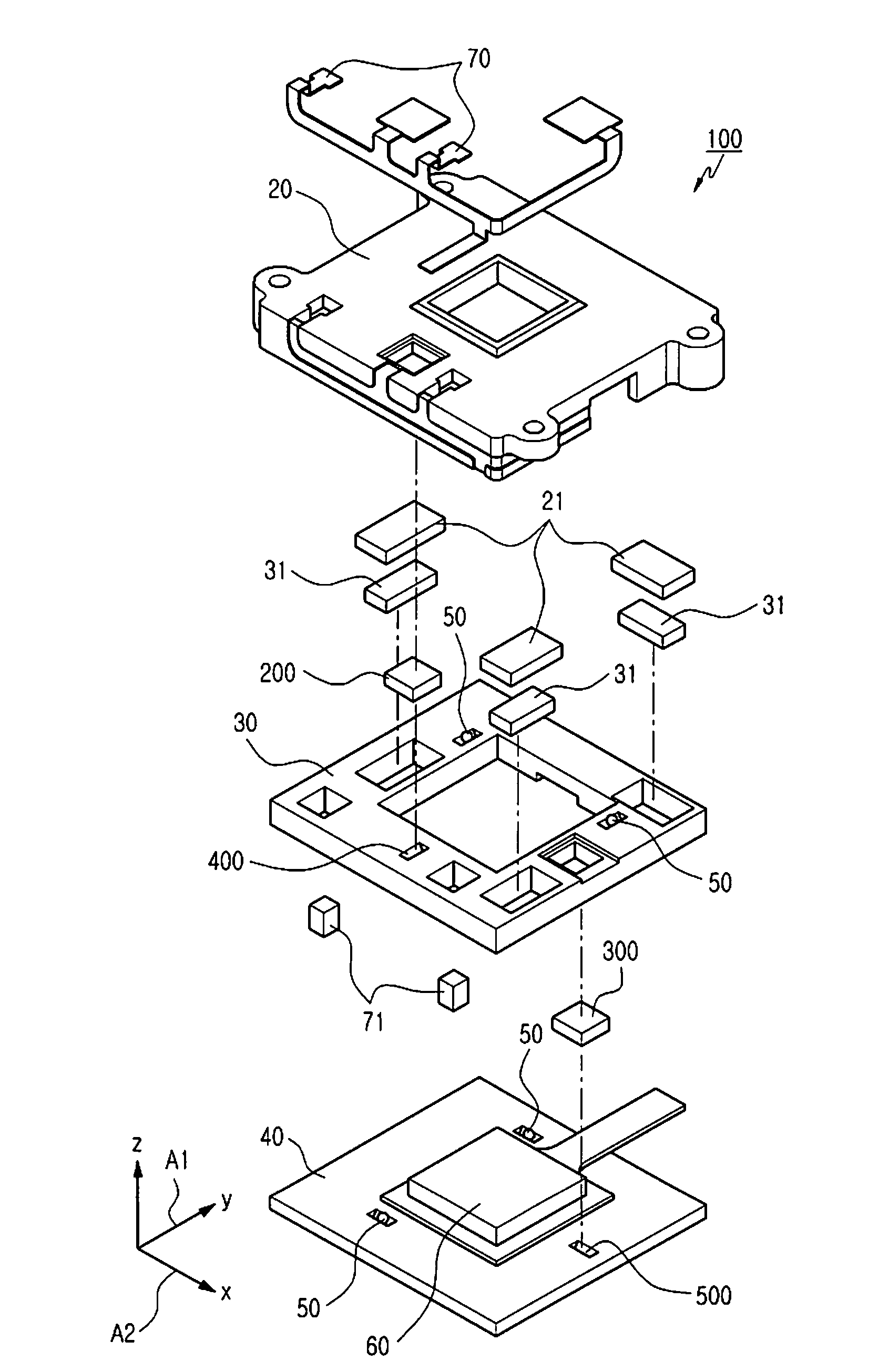
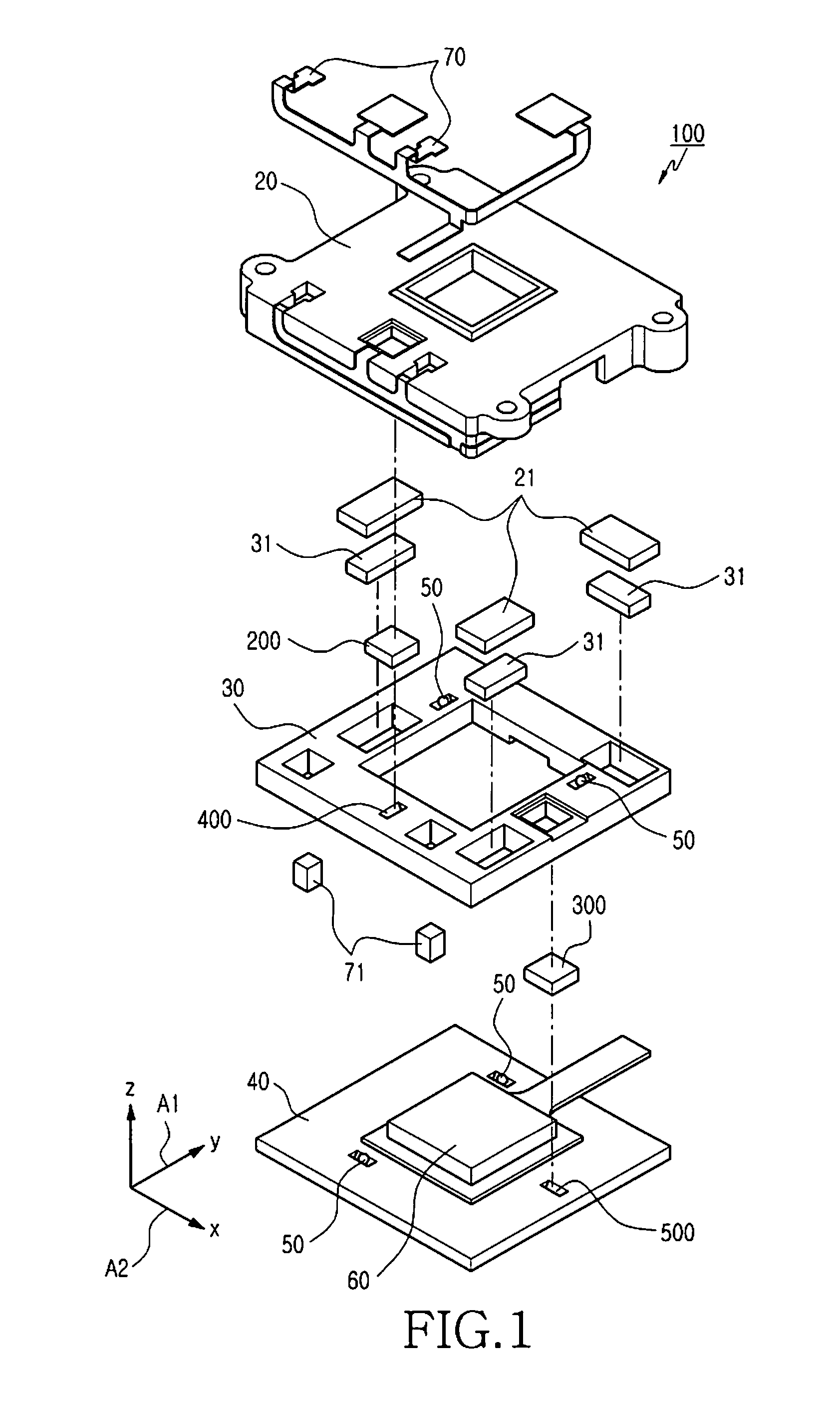
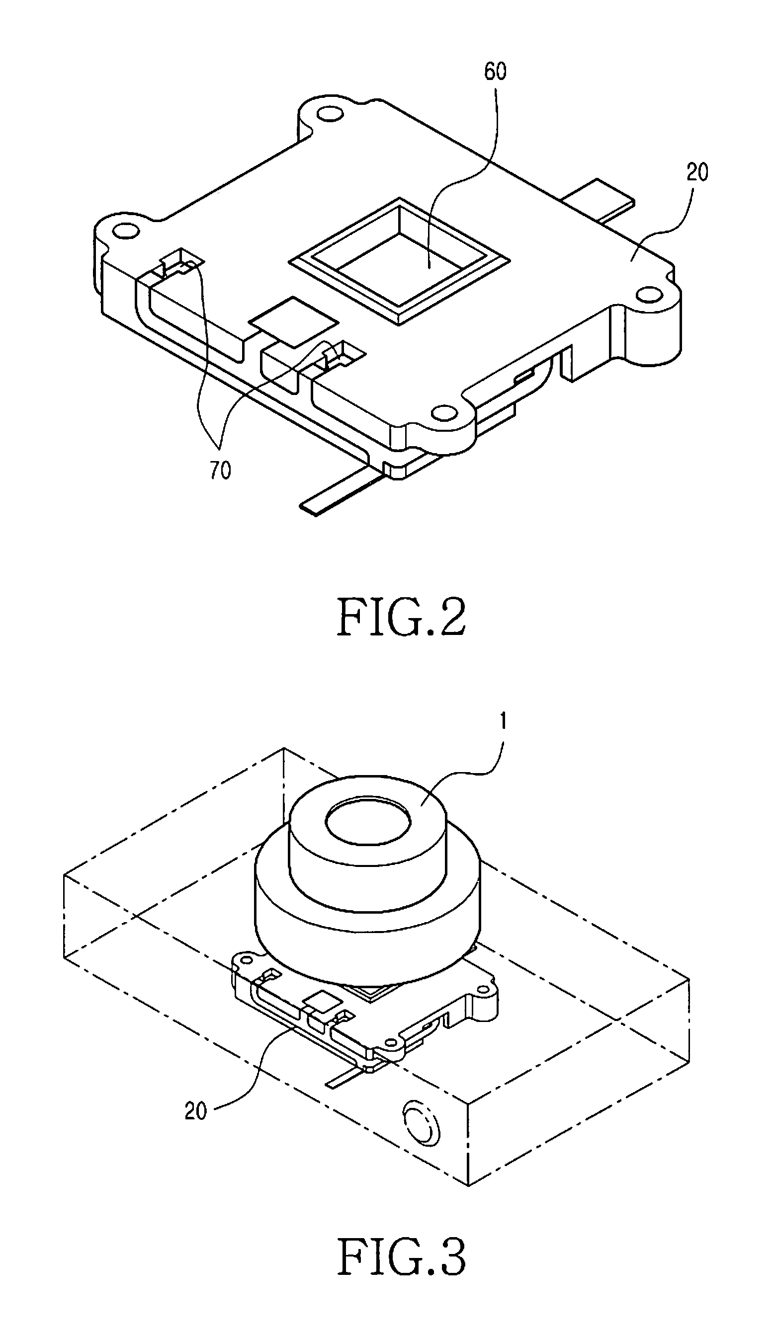
[0027]As shown in FIGS. 1 through 10, an optical image stabilizer 100 for a camera module assembly 1 includes a housing 20, first and second drive plates 30 and 40, one or more ball bearings 50, first and second drive portions 200 and 300, and first and second guide portions 400 and 500. The housing 20 is configured to include the first and second drive plates 30 and 40, the ball bearings 50, the first and second drive portions 200 and 300...


PUM


Abstract

Provided is an optical image stabilizer for a camera module assembly including at least one or more guide portions for guiding linear movement while preventing friction in first and second drive portions. The optical image stabilizer includes a first drive portion including a tip provided between a housing and a first drive plate to drive the first drive plate in a first direction, a second drive portion including a tip provided between the first drive plate and a second drive plate to drive the second drive plate in a second direction, and first and second guide portions formed in the first and second drive plates in positions corresponding to the tips of the first and second drive portions such that the first and second guide portions guide linear movement of the tips and prevent friction when the first and second drive portions are driven in the first and second directions.

Description

PRIORITY[0001]This application claims priority under 35 U.S.C. §119(a) to a Korean Patent Application filed in the Korean Intellectual Property Office on Jun. 3, 2009 and assigned Serial No. 10-2009-0048843, the contents of which are incorporated herein by reference.BACKGROUND OF THE INVENTION[0002]1. Field of the Invention[0003]The present invention relates to an optical image stabilizer for a camera module assembly, in which one or more guide portions for guiding linear movement while preventing friction are provided in first and second drive portions.[0004]2. Description of the Related Art[0005]With the recent proliferation of digital still and video cameras, there is an increasing demand for photographing high-quality still and moving pictures. In particular, a Complementary Metal Oxide Semiconductor (CMOS) sensor has replaced a Charge Coupled Device (CCD) sensor as a photographing device for a digital camera, because although the CCD sensor is superior to the CMOS sensor in ter...

Claims


Application Information

Patent Timeline
Patent Type & Authority Patents(United States)
IPC IPC(8): H04N5/228G03B17/00
CPCG02B27/646H04N5/23248H04N5/2257H04N5/2253H04N23/54H04N23/57H04N23/68H04N23/687
Inventor KO, KIL-SOOSHIN, DOO-SIK
Owner HUAWEI TECH CO LTD
Why Eureka
Try Eureka