Method for allocating reference signals in MIMO system

a reference signal and antenna system technology, applied in the field of wireless communication, can solve problems such as adversely affecting the data ra

Active Publication Date: 2012-05-08
LG ELECTRONICS INC
View PDF13 Cites 21 Cited by
  • Summary
  • Abstract
  • Description
  • Claims
  • Application Information

AI Technical Summary

Problems solved by technology

But, this may adversel

Method used


Image

  • Method for allocating reference signals in MIMO system
  • Method for allocating reference signals in MIMO system
  • Method for allocating reference signals in MIMO system

Examples


Embodiment Construction

[0027]Additional features and advantages of the invention will be set forth in the description which follows, and in part will be apparent from the description, or may be learned by practice of the invention. It is to be understood that both the foregoing general description and the following detailed description of the present invention are exemplary and explanatory and are intended to provide further explanation of the invention as claimed.

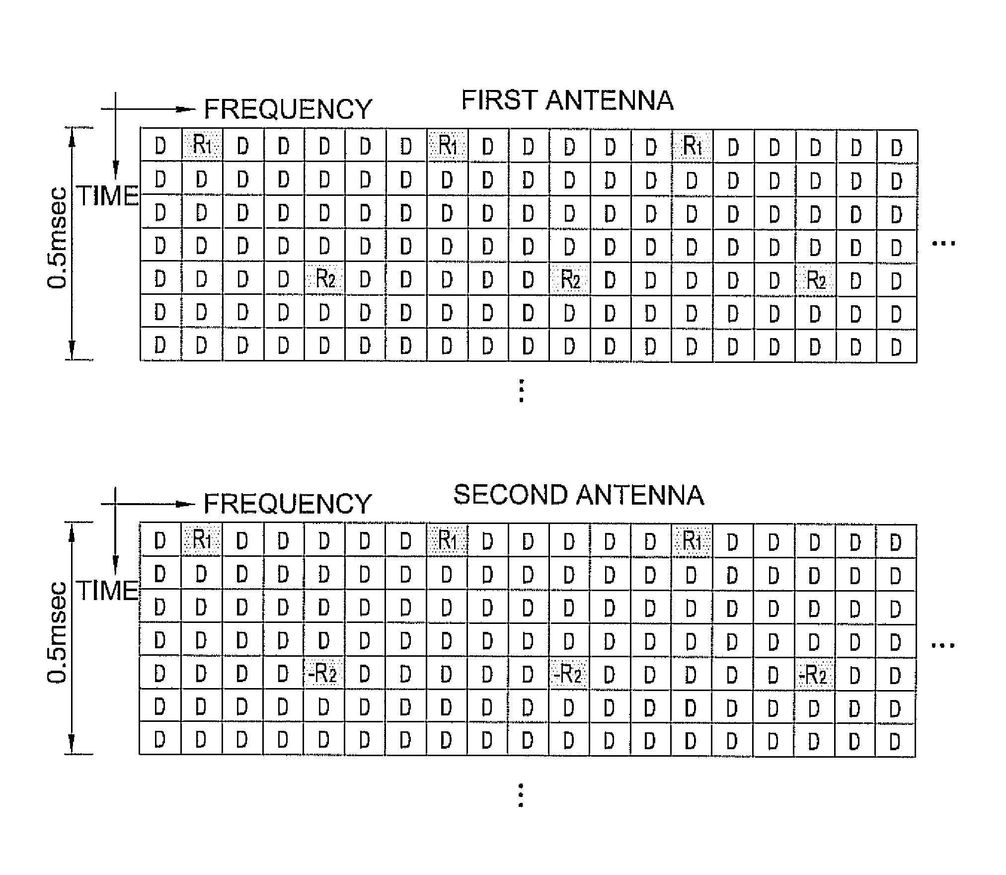
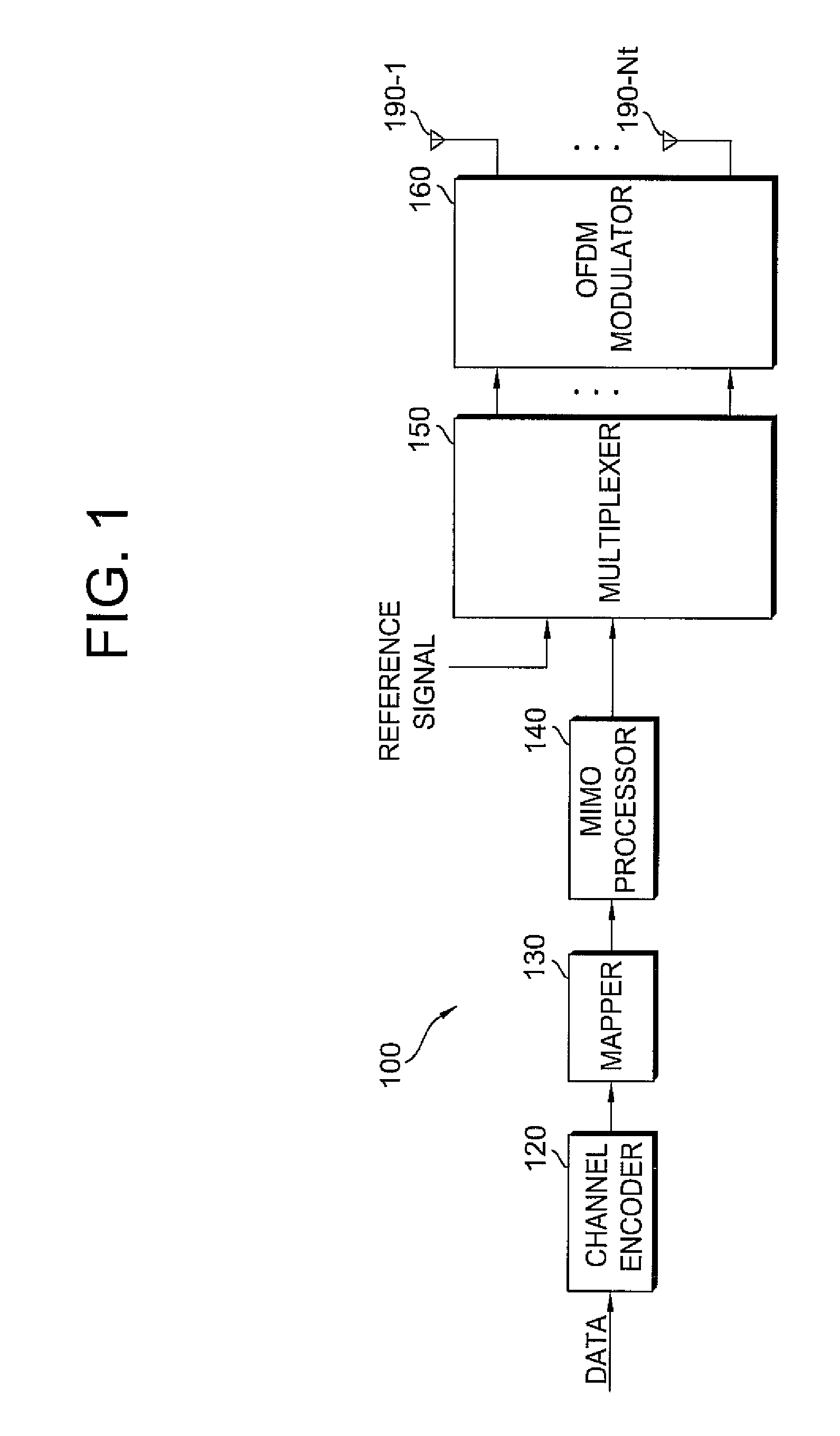
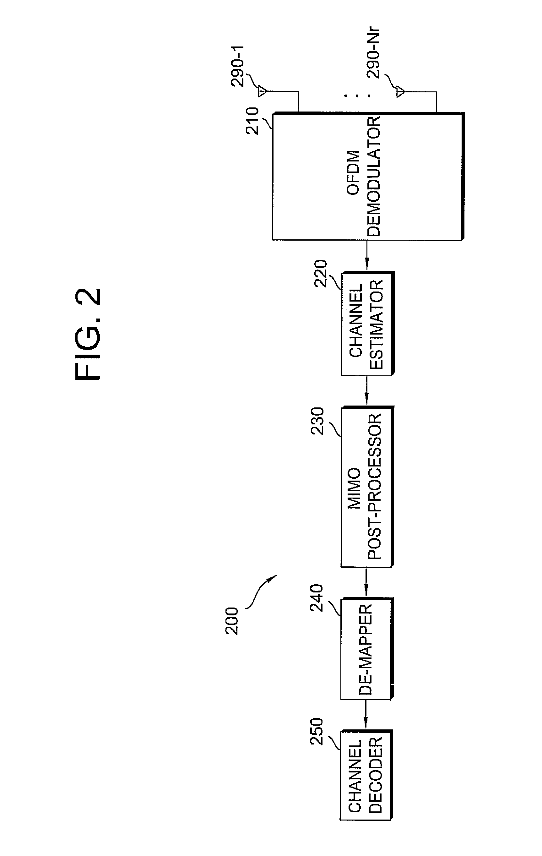
[0028]The technique to be described below may be used in various communication systems. The communication systems are widely distributed so as to provide various communication services (e.g. voice, packet data, etc). The technique may be used for downlink or uplink. In general, downlink means communication from a base station (BS) to user equipment (UE), and uplink means communication from the UE to the BS. The BS is generally referred to a fixed station that communicates with the UE and may also be referred to as another terminology such as a n...


PUM


Abstract

There is provided a method for placing reference signals in a wireless communication system. The method includes preparing a plurality of sub-frames for a plurality of antennas, placing a reference signal for one sub-frame and placing a reference signal for another sub-frame not to overlap with the reference signal for one sub-frame, wherein the reference signal for one sub-frame and the reference signal for another sub-frame are successively placed on contiguous OFDM symbols or on the contiguous sub-carriers. Channel estimation or data demodulation can be prevented from performance degradation.

Description

CROSS-REFERENCE TO RELATED APPLICATIONS[0001]This application claims the benefit of priority of U.S. Provisional application Ser. No. 60 / 791,833, filed on Apr. 12, 2006, U.S. Provisional application Ser. No. 60 / 828,950, filed on Oct. 10, 2006, U.S. Provisional application Ser. No. 60 / 829,273, filed on Oct. 12, 2006, U.S. provisional application Ser. No. 60 / 863,775, filed on Oct. 31, 2006, and U.S. Provisional application Ser. No. 60 / 910,183, filed on Apr. 4, 2007, which are incorporated by reference in their entirety herein.BACKGROUND[0002]1. Technical Field[0003]The present invention relates to wireless communication, and more particularly, to a method for allocating reference signals in a multiple-input multiple-output (MIMO) antenna system.[0004]2. Related Art[0005]A multiple-input multiple-output (MIMO) system is defined as a system that improves data communication efficiency by the use of multiple transmit antennas and multiple receive antennas. The MIMO system may be realized ...

Claims


Application Information

Patent Timeline
IPC IPC(8): H04J11/00
CPCH04B7/0613H04B7/0684H04L5/0048H04B7/0413H04L25/0226H04L25/0224H04L5/0023
Inventor KO, HYUN SOOIHM, BIN CHULCHUN, JIN YOUNGLEE, WOOK BONGCHUNG, JAE HOONCHANG, JAE WONJUNG, JIN HYUKLEE, MOON ILHAN, SEUNG HEE
Owner LG ELECTRONICS INC
Why Eureka
Try Eureka