Location system

a technology of location system and location information, applied in the direction of navigation instruments, instruments, transportation and packaging, etc., can solve the problems of not providing automatic updates of changing aircraft location information, significant hazard of runway incursions on airfields, and significant increase in the risk of collisions between arriving and departing aircra

Active Publication Date: 2012-05-08
WOEHLER DOUGLAS EDWARD
View PDF35 Cites 57 Cited by
  • Summary
  • Abstract
  • Description
  • Claims
  • Application Information

AI Technical Summary

Problems solved by technology

Runway incursions are a significant hazard for aircraft taxiing on airfields.
In low visibility conditions, runway incursions can significantly increase the risk of collisions between arriving and departing aircraft.
While such approaches are economical to implement, they rely heavily on pilot skill to be effective and do not provide automated updates of changing aircraft location information to air traffic control personnel.
However, while these systems are capable of indicating the location of an object, the object is not identified.
Furthermore, these systems can be costly to implement and often do not integrate easily with existing airfield runway control systems.

Method used


Image

  • Location system
  • Location system
  • Location system

Examples


Embodiment Construction

[0016]In the following detailed description of the preferred embodiments, reference is made to the accompanying drawings, which form a part hereof, and in which is shown by way of illustration specific embodiments in which the invention may be practiced. It is to be understood that other embodiments may be utilized and structural or logical changes may be made without departing from the scope of the present invention. The following detailed description, therefore, is not to be taken in a limiting sense, and the scope of the present invention is defined by the appended claims.

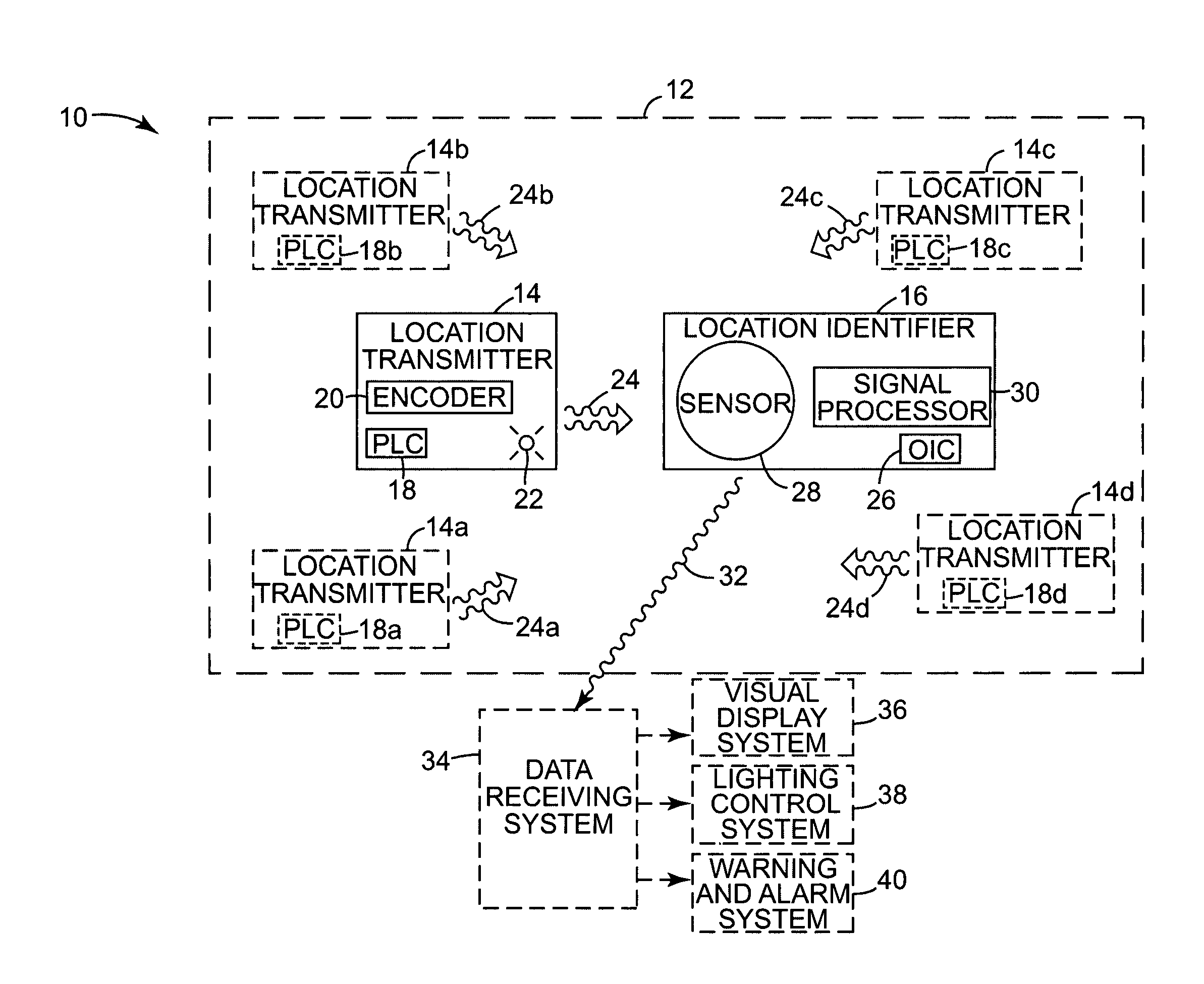
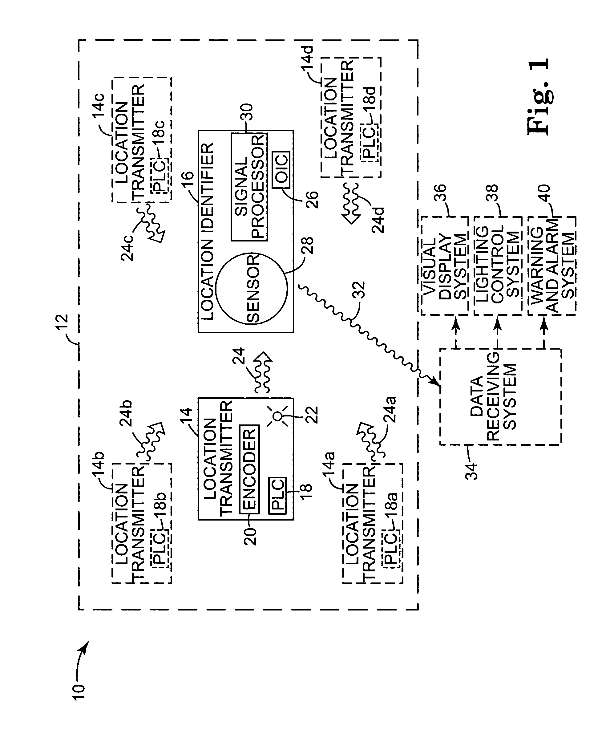
[0017]FIG. 1 illustrates generally one exemplary embodiment of a ground surface location system 10 according to the present invention for identifying a location of an object within a coverage area 12. Ground surface location system 10 includes a location transmitter system 14 and a location identifier system 16. Location transmitter system 14 includes a physical location code (PLC) 18 stored therein that corresp...


PUM


Abstract

One embodiment of the present invention provides a ground surface location system for identifying an object and its location within a coverage area. The ground surface location system includes a location transmitter and a location identifier. The location transmitter is positioned at a location within the coverage area and has a physical location code corresponding to the location stored therein, and is configured to provide an optical signal representative of the physical location code. The location identifier is adapted to couple to the object and has an object identification code representative of the object stored therein, and is configured to receive the optical signal and to transmit an identification signal representative of the physical location code and the object identification code.

Description

CROSS REFERENCE TO RELATED APPLICATION[0001]The subject matter of this application is related to the subject matter of U.S. Provisional Patent Application No. 60 / 418,932, filed Oct. 15, 2002, priority to which is claimed under 35 U.S.C. §119(e) and which is incorporated herein by referenceTHE FIELD OF THE INVENTION[0002]The present invention relates generally to location systems, and more particularly to a ground surface location system utilizing optical signals representative of location information.BACKGROUND OF THE INVENTION[0003]Runway incursions are a significant hazard for aircraft taxiing on airfields. In low visibility conditions, runway incursions can significantly increase the risk of collisions between arriving and departing aircraft. To reduce the risk of incursions, low visibility taxi plans have been developed and are employed when takeoff and landing operations have less than a specified runway distance available. Stop bars have been installed at runway intersections ...

Claims


Application Information

Patent Timeline
Patent Type & Authority Patents(United States)
IPC IPC(8): G01C21/00G06F17/00G08G5/06B64D47/02
CPCG01C21/20G01S5/0045G01S5/16G08G5/045G08G5/065
Inventor WOEHLER, DOUGLAS EDWARD
Owner WOEHLER DOUGLAS EDWARD
Why Eureka
Try Eureka