Recovery method and radio network controller in radio communication system

a radio communication system and radio network controller technology, applied in the field of recovery methods and radio network controllers in radio communication systems, can solve the problem that the radio network controller cannot execute the recovery procedure autonomously, and achieve the effect of reducing the recovery time in failures

Inactive Publication Date: 2012-05-15
FUJITSU LTD
View PDF14 Cites 0 Cited by
  • Summary
  • Abstract
  • Description
  • Claims
  • Application Information

AI Technical Summary

Benefits of technology

[0015]It is an object of the present invention to reduce the time required for recovery in failure occurrence in a radio communication system. It is another object of the present invention to enable a network apparatus to perform autonomous failure recovery in a radio communication system.
[0017]According to the method, because a data path is maintained when the mobile station control units are switched, the time required for recovery is reduced as well as reducing influence on the communication of the mobile station.
[0021]According to the above configuration, because a data path is maintained when the mobile station control units are switched, influences on the communication of the mobile stations are reduced.
[0022]The second mobile station control unit may initialize a communication parameter relating to communication of the mobile station, and may control communication of the mobile station using the initialized communication parameter. Alternatively, the second mobile station control unit may obtain a commutation parameter relating to communication of the mobile station from the mobile station, and may control communication of the mobile station using the obtained communication parameter. According to these configurations, the radio network controller can start recovery procedure autonomously without the request from the mobile station.
[0023]According to the present invention, it is possible to reduce recovery time in failure occurrence in a radio communication system. In addition, according to another mode of the present invention, a network apparatus can perform autonomous failure recovery in a radio communication system.

Problems solved by technology

In other words, the radio network controller could not execute the recovery procedure autonomously.
Note that the above problem can occur not only in the case of an MS control signalling device failure but also in a case that a failure occurs on a route for transmitting an MS control signal and in a case that the service is suspended due to blockage etc.

Method used


Image

  • Recovery method and radio network controller in radio communication system
  • Recovery method and radio network controller in radio communication system
  • Recovery method and radio network controller in radio communication system

Examples


Embodiment Construction

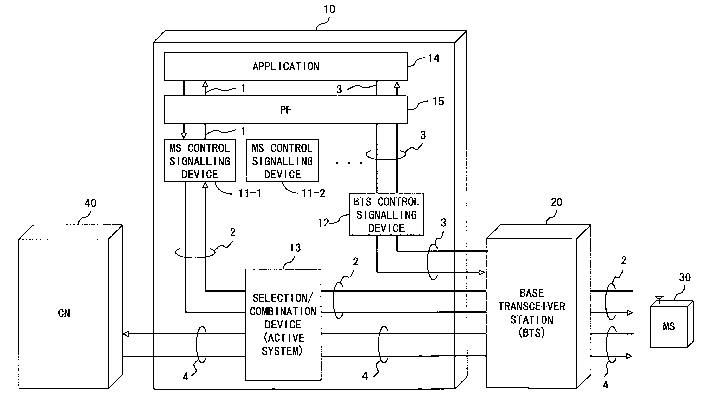
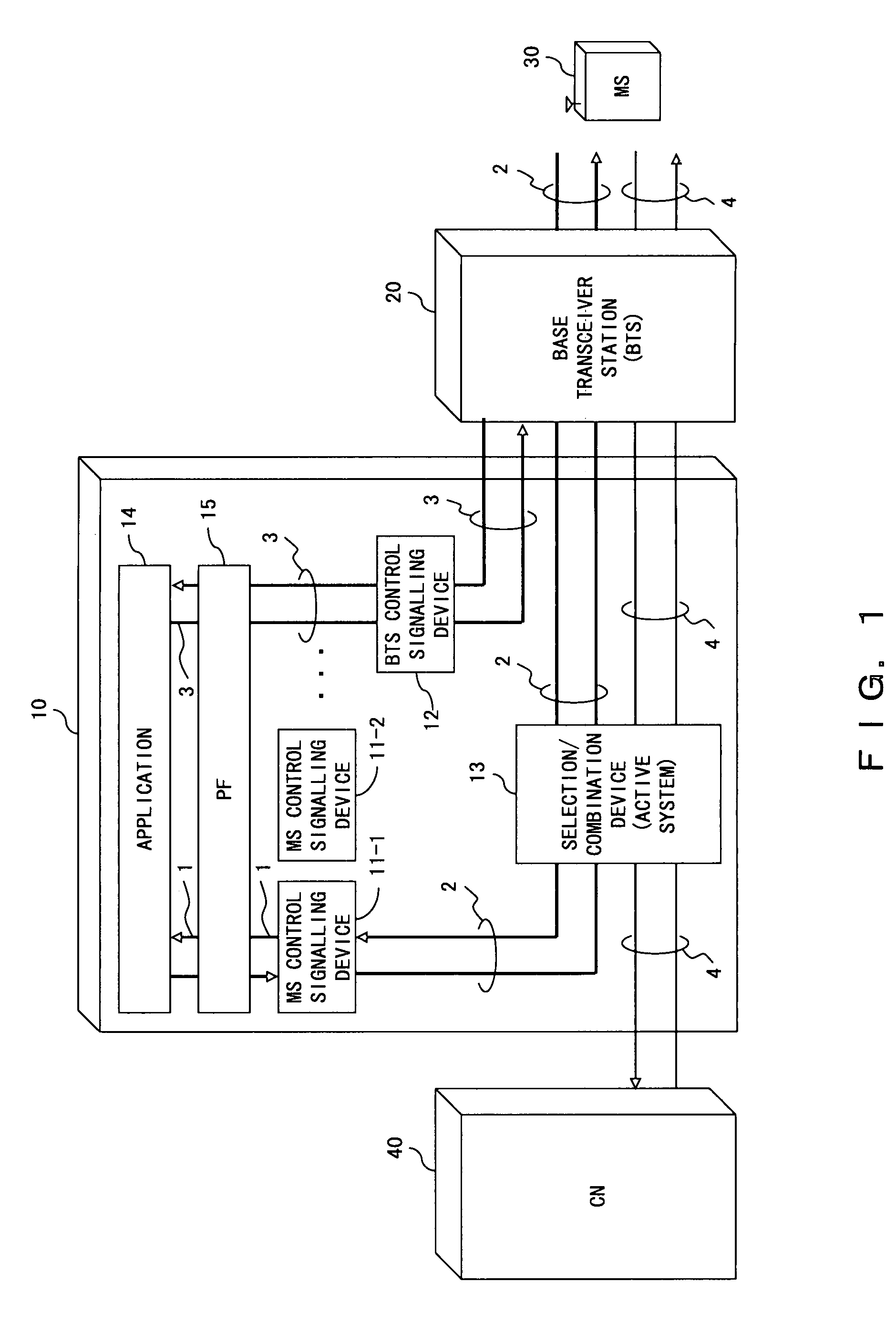
[0031]In the following description, a radio network controller and a recovery method of the embodiments of the present invention are set forth with reference to the drawings. The description assumes a radio communication system specified by 3GPP. In other words, a radio communication system comprises abase transceiver station (BTS or node B) and a radio network controller (RNC), and a mobile station (MS or UE) is accommodated by the nearest base transceiver station. Note that a basic configuration of the radio network controller is the same as explained with reference to FIG. 1.

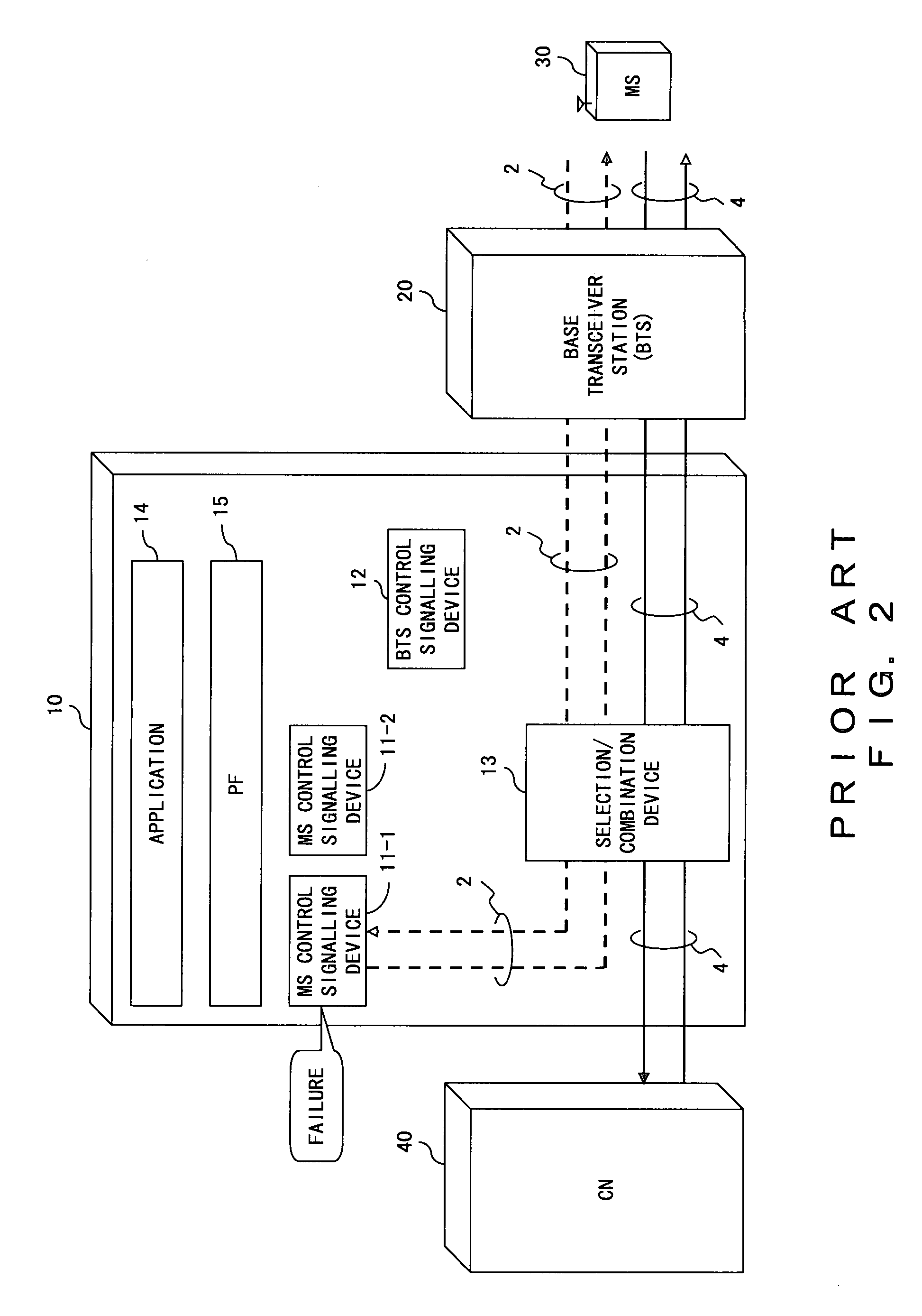
[0032]FIG. 6 through FIG. 9 are diagrams explaining recovery procedures in a radio network controller when an MS control signalling device fails. Here, a radio network controller 10 comprises a plurality of MS control signalling devices 11 (11-1, 11-2, . . . ), and the MS control signalling device 11-1 is assigned to a mobile station 30. In such a case, an MS control signal 2 is transmitted / received between t...


PUM


Abstract

When a first MS control signalling device that controls a mobile station fails, a second MS control signalling device takes over the processing of the first MS control signalling device. The second MS control signalling device requests a RLC parameter necessary for communication of the mobile station, and the mobile station transmits the requested RLC parameter to the second MS control signalling device. The second MS control signalling device controls communication of the mobile station, using the obtained RLC parameter. A data path for transmitting user data of the mobile station is not released but is held when the MS control signalling devices are switched.

Description

BACKGROUND OF THE INVENTION[0001]1. Field of the Invention[0002]The present invention relates to a recovery method in a case of failure on a route for transmitting a control signal in a radio communication system, and to a radio network controller comprising such a recovery function.[0003]2. Description of the Related Art[0004]Radio communication systems such as a mobile communication system comprise a plurality of base transceiver stations (BTS) (also referred to as node B), and mobile stations (MS) (also referred to as user equipment (UE)) such as cellular phone devices are accommodated by the nearest base transceiver station. A radio network controller (RNC) is connected to a single or a plurality of base transceiver station(s). The radio network controller controls the base transceiver station(s), and also controls mobile stations accommodated by the base transceiver station.[0005]FIG. 1 is a diagram showing a configuration of a radio network controller. In the diagram, a config...

Claims


Application Information

Patent Timeline
Patent Type & Authority Patents(United States)
IPC IPC(8): H04B1/38H04B17/00H04W24/00H04W24/04H04W88/12
CPCH04B1/74H04W24/04H04W88/12
Inventor YOSHIDA, HIDEAKIMUNAKATA, YUJI
Owner FUJITSU LTD
Why Eureka
Try Eureka