
Levelling device for the placing of pieces for covering floors and similar

a technology of leveling device and floor, which is applied in the direction of roofs, building material handling, construction, etc., can solve the problems of hard and annoying job, process is annoying and time-consuming, and the placing of pieces for covering floors is difficult and annoying

Active Publication Date: 2012-05-22
GERMANS BOADA SA
View PDF21 Cites 78 Cited by
  • Summary
  • Abstract
  • Description
  • Claims
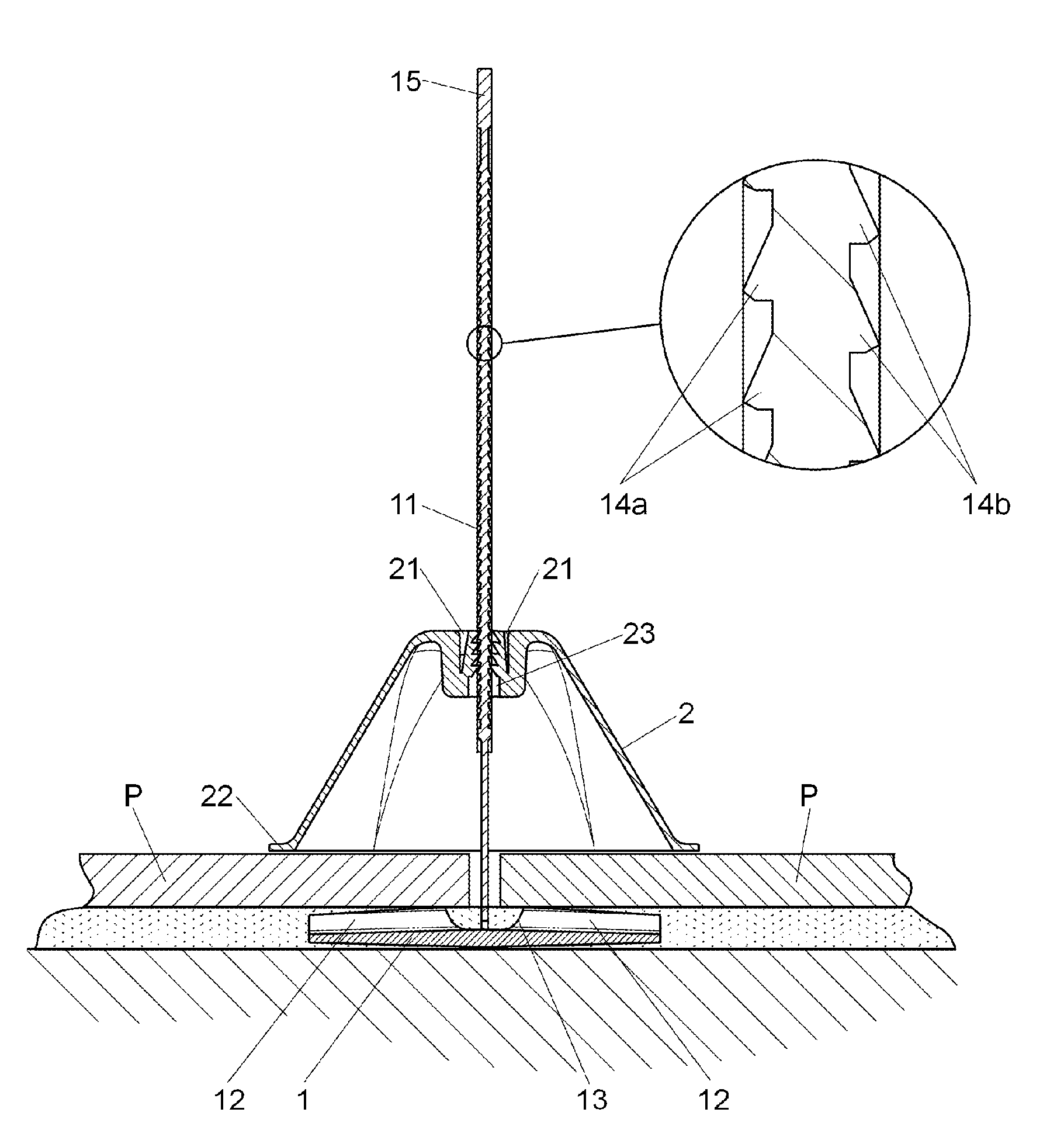
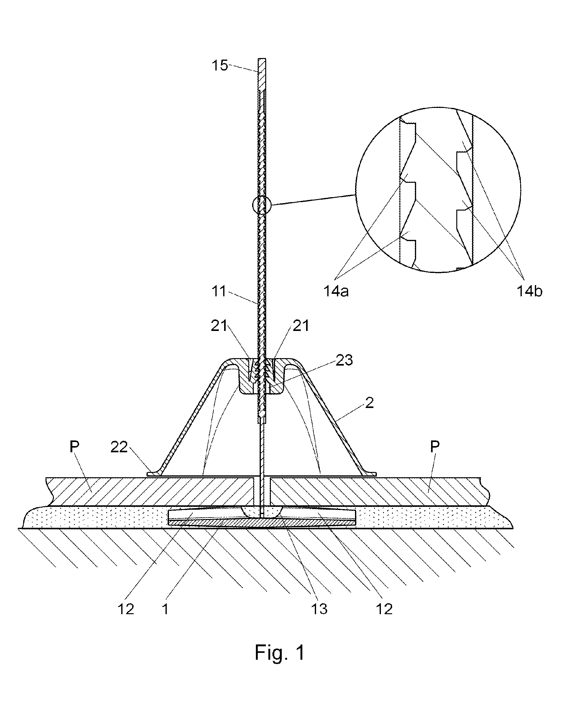
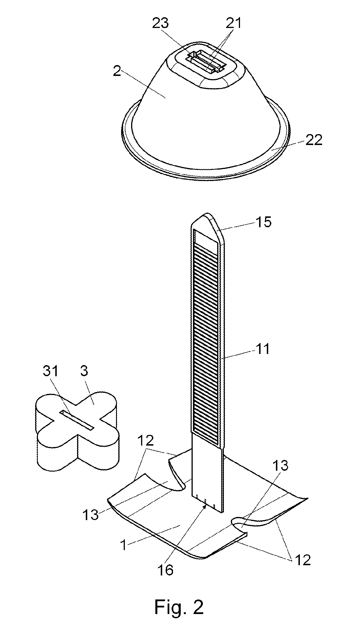
  • Application Information

AI Technical Summary

Benefits of technology

[0009]The leveling device for placing covering pieces which is the subject of the invention has technical features aimed at facilitating the job of placing and aligning the covering pieces to obtain the leveling of the pieces on floors, ceilings, vertical and inclined walls, absorbing the irregularities of the substrate by means of the adhesive layer, as well as the geometrical irregularities of the covering pieces or the shrinking produced during the setting of the mortar or adhesive, which may generate undesired movements of the pieces already placed on the substrate. The device makes the annoying leveling operations easier, reducing the time used for the leveling of the covering pieces. Furthermore it directly permits the reduction of the assembly costs. This reduction of the working time reduces as well the strain on the operator for reducing the time during which he is submitted to inadequate postures, above all when carrying out the works on floors, walls or ceilings, improving the ergonomic conditions of work for the operator.
[0010]According to the invention, the flexible post has a rectangular cross section with two major sides which respectively have mutually opposed toothings, with teeth which are offset among each other and the passage in the second body has two latching pawls for holding said teeth which are parallel and mutually opposed. In this way, in an operative position of the device, the teeth of the flexible post engage in alternative form said pawls, obtaining a higher precision and control of the advance and the pressure exerted by said bodies on the aligned covering pieces, by permitting that during the advancement for the securement of the second body one side or the other of the flexible post is always engaged at a distance which is substantially shorter than in the case of using only one toothing. It has been foreseen as well that the second body has a bell like hollow form with a widened lower contact mouth or border to distribute the pressure on the pieces of the covering. This permits to obtain a higher rigidity of the second body than in the case of using flat parts, excluding the need of rigidifying metal inserts. Besides, the pressure action distributed by an external circle prevents the formation of high pressure points such as a raised corner of a covering piece or a particle of material introduced between said covering piece and the second covering piece, which would result in a faulty alignment.
[0011]The second body is optionally transparent, this contributing to a better control of the positioning of the device on the covering pieces to be aligned, especially in difficult corners and joints. However, it is not to be discarded that said second body may be of a non-transparent colour in less stringent applications.
[0012]The first body has curved perimetral borders opposed one another in form of thin and flexible flanges directed towards the same side of the flexible post. Said flexible flanges have at least one notch or recess in its intermediate part, separating independent support parts to rest on the independent covering pieces. These flexible flanges permit that the support of the covering piece may be well balanced independently that the contact point of the first body takes place on the back portion of the covering piece directly on its flat surface or on one of the recesses or protrusions which usually have to ensure the retention with the adhesive.
[0013]To facilitate the convenient introduction of the second or bell like body within the flexible post it has been provided that the free end of said flexible post has a tapering cross section. For instance, it may show an oblique or arrow like form, thus facilitating the entry of the second body and the tightening tool.

Problems solved by technology

This process is annoying and time consuming.
The process has to be carried out carefully as at the moment of the placing of the covering pieces the layer of mortar or adhesive being used is soft and although the receiving lower surface or substrate may be completely smooth, the covering pieces may be somewhat tilted and not level, with the result of a faulty finishing of the covering.
This job is to be carried out repeatly for all the pieces of the covering so that it is a hard and annoying job as the operator has to work in an uncomfortable position during the whole working time, this being especially true in case of floor coverings.
This system suffers from the inconvenience that the threaded screw and nut parts may be soiled with the mortar or adhesive being therefore difficult its withdrawal later on.
However, to ensure that the sufficient alignment pressure may be carried out, the teeth have substantial dimensions and the pitch separating them is also sizeable.
This purports that the adjustment of the alignment can not be carried out with the sufficient precision in the advance movement and with the sufficient pressure, as the engagement between the blocking plate in a given tooth of the toothing may finally be somewhat loose and the gearing with the next tooth can not be obtained or the pressure may be excessive, this resulting in a faulty assembly.
For the securement of the upper plate on the post in an adequate position a metal insert is used for its sideways introduction, engaging in one of the multiple notches which have been made crosswise in said post, this not permitting to regulate the pressure in a progressive and precise way as said notches are substantially separate between each other, so they don not permit a progressive introduction.

Method used


Image

  • Levelling device for the placing of pieces for covering floors and similar
  • Levelling device for the placing of pieces for covering floors and similar
  • Levelling device for the placing of pieces for covering floors and similar

Examples


Embodiment Construction

[0009]The leveling device for placing covering pieces which is the subject of the invention has technical features aimed at facilitating the job of placing and aligning the covering pieces to obtain the leveling of the pieces on floors, ceilings, vertical and inclined walls, absorbing the irregularities of the substrate by means of the adhesive layer, as well as the geometrical irregularities of the covering pieces or the shrinking produced during the setting of the mortar or adhesive, which may generate undesired movements of the pieces already placed on the substrate. The device makes the annoying leveling operations easier, reducing the time used for the leveling of the covering pieces. Furthermore it directly permits the reduction of the assembly costs. This reduction of the working time reduces as well the strain on the operator for reducing the time during which he is submitted to inadequate postures, above all when carrying out the works on floors, walls or ceilings, improvin...


PUM


Abstract

The device has a first lower substantially flat body, which has in its upper part a flexible post with a narrowed or weakened portion and a second upper body with the passage for receiving and securing said post. The flexible post, which has a rectangular cross section, has in its main surfaces respective mutually opposed toothings, which teeth are offset in the lengthwise direction and the passage of the second body has two latching pawls mutually opposed, so that in the operative position of the devices, the teeth of the flexible post engage in an alternate form with said latching pawls. The second body has a bell like hollow form with a lower widened contact mouth or border.

Description

SUBJECT OF THE INVENTION[0001]The invention refers to a leveling device for placing pieces for covering floors and similar, that is, a leveling device especially adequate for the placing of adjacent ceramic pieces, panels or tiles correctly aligned and leveled.BACKGROUND OF THE INVENTION[0002]For the placing of flat covering pieces such as ceramic pieces, tiles and other similar with a substantially uniform thickness on the floor, walls or other substrates, a holding layer of mortar or adhesive is used on which the covering pieces are located. This operation requires a certain precision from the side of the operator in order that afterwards the surface which bears the covering pieces shows a smooth and sufficiently level finishing. This process is annoying and time consuming. Each of the pieces has to be placed, leveled and left flush with the adjacent pieces already placed, in an individual and completely artisanal form.[0003]The process has to be carried out carefully as at the mo...

Claims


Application Information

Patent Timeline
Patent Type & Authority Patents(United States)
IPC IPC(8): E04F21/18
CPCE04F21/0092
Inventor TORRENTS I COMAS, JOSEP
Owner GERMANS BOADA SA
Learn More