Vacuum insulating glass unit with viscous edge seal

a technology of viscous edge seal and vacuum insulation glass, which is applied in the direction of mechanical equipment, special door/window arrangements, transportation and packaging, etc., can solve the problems of sustained stress in the glass sheet, insignificant viscous shear stress, and inability to contribute to the fracture of the glass sheet or noticeable bulging of the glass sheet, etc., to reduce the risk of ceramic glass scratching, less hardness, and less thermal conductivity

Inactive Publication Date: 2012-05-22
JONES ROBERT S
View PDF14 Cites 13 Cited by
  • Summary
  • Abstract
  • Description
  • Claims
  • Application Information

AI Technical Summary

Benefits of technology

[0055]Another aspect of the invention provides methods for forming an edge seal for a vacuum insulating glass unit comprising a first glass sheet and a second glass sheet and at least one spacer in between the first and second glass sheets configured to contribute to the separation of the first and second glass sheets. In one embodiment, the method comprises sealing the edge of the vacuum insulating glass unit with an edge seal which, together with the first and second glass sheets, defines a vacuum space in between the first and second glass sheets; evacuating the vacuum space through a pump out port to a pressure less than atmospheric pressure; and sealing the pump out port. The edge seal in this embodiment being configured to allow relative lateral movement between the first and second glass sheets when the first and second glass sheets experience differential thermal strain and comprising: a viscous material, wherein the viscous material restricts the rate at which gas permeates into the vacuum space when it is at a pressure less than atmospheric pressure and further wherein there is viscous shear in at least a portion of the viscous material when there is relative lateral movement between the first and second glass sheets; and at least one barrier whose configuration constrains the viscous material. Sealing the edge of the vacuum insulating glass unit in this embodiment can be accomplished, for example, by pumping the viscous material in between the first and second glass sheets through one or more entry holes disposed along the periphery of at least one of the first and second glass sheets; directing, via a pressure differential, the viscous material to flow to one or more exit holes disposed along the periphery of at least one of the first and second glass sheets; and sealing the entry and exit holes. An example of a method of forming an edge seal in accordance with this embodiment is shown in FIGS. 13 and 14, and is described in greater detail in the Detailed Discussion section, below.

Problems solved by technology

Because the gap is bridged by a viscous material that undergoes viscous shear with very low shear stress, when the glass sheets move relative to one another the stresses in the glass sheets resulting from those viscous shear stresses are insignificant and cannot contribute to fracture of the glass sheets or noticeable bulging of the glass sheets.
This is not the case for edge seals made entirely of elastic materials where static relative displacement results in sustained stress in the glass sheets.

Method used


Image

  • Vacuum insulating glass unit with viscous edge seal
  • Vacuum insulating glass unit with viscous edge seal
  • Vacuum insulating glass unit with viscous edge seal

Examples


first embodiment

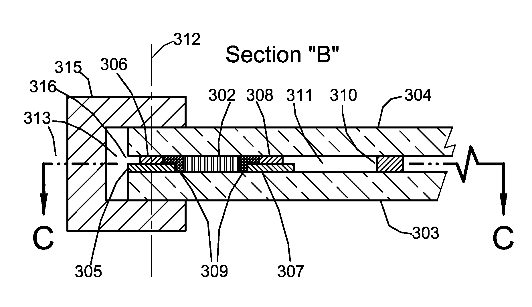
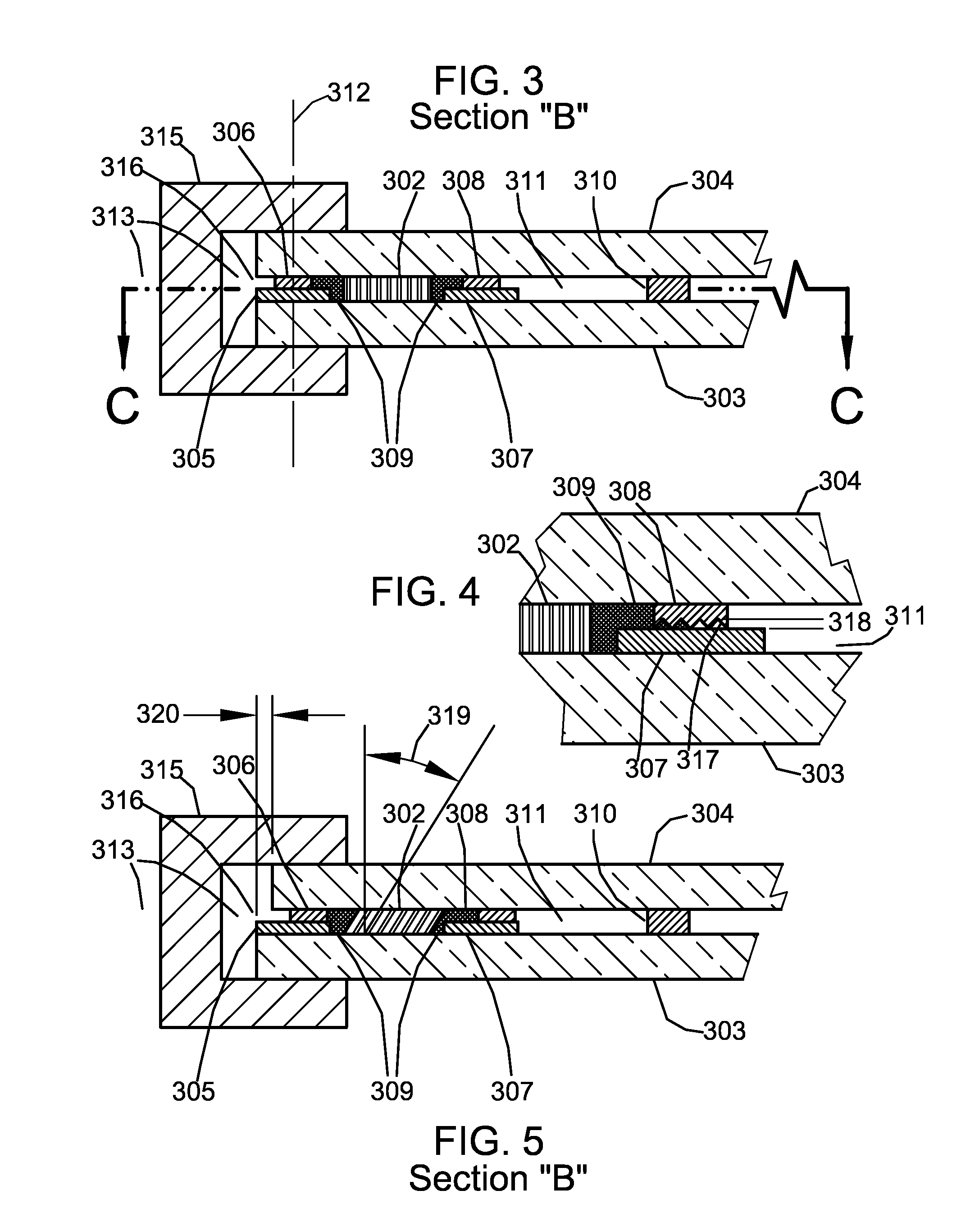
[0073]FIG. 3 is a cross sectional view (as referenced by FIG. 1) of the edge region of a VIG unit according to this invention showing an edge seal that comprises viscous material 302 with low gas permeability and barriers that constrain viscous material 302 that include: glass sheets 303 and 304; strip spacers 305, 306, 307, 308; and lubricating low vapor pressure viscous barrier 309. Strip spacers 305, 306, 307, 308 may be made of 420 stainless steel, which has virtually the same coefficient of thermal expansion as soda lime glass, or they may be made of PE Polyethylene or other suitable polymers.

[0074]FIG. 3 shows the edge region under the condition that the ambient air temperatures on either side of the unit are the same, as would occur if the unit was in service in a building and the indoor and outdoor temperatures were the same. Glass sheets 303 and 304 are separated by an array of spacers 310. The thickness of spacers 310, and therefore the distance between glass sheets 303 an...

second embodiment

[0096]FIG. 8 is a cross sectional view (as referenced by FIG. 1) of the edge region of a VIG unit according to this invention showing an edge seal that comprises viscous material 802 with low gas permeability and barriers to constrain viscous material 802 that include: glass sheets 803 and 804; strip spacers 805, 806, 807, and 808; lubricating low vapor pressure viscous barrier 809; and end cap 815. FIG. 8 shows the edge region under the condition that the ambient air temperatures on either side of the unit are the same, as would occur if the unit was in service in a building and the indoor and outdoor temperatures were the same. Viscous material 802 with low gas permeability and viscous barrier 809 may continue unbroken around the edge regions of glass sheets 803 and 804. Strip spacers 805, 806, 807, 808, and end cap 815 may continue unbroken around the edge regions of glass sheets 803 and 804. End cap 815 may place a clamping or compressive force against glass sheets 803 and 804. ...

third embodiment

[0097]FIG. 9 is a cross sectional view (as referenced by FIG. 1) of the edge region of a VIG unit according to this invention showing an edge seal that comprises viscous material 902 with low gas permeability and barriers to constrain viscous material 902 that include: glass sheets 903 and 904, elastic membrane 905, and end cap 906. Elastic membrane 905 is cemented or otherwise affixed to glass sheets 903 and 904. Elastic membrane 905 need not have low gas permeability so it can be made of a material and with a thickness that stretches easily and with very little force. FIG. 9 shows the edge region under the condition that the ambient air temperatures on either side of the unit are the same as would occur if the unit was in service in a building and the indoor and outdoor temperatures were the same. Glass sheets 903 and 904 are separated by an array of spacers 907 and by strip spacer 908. Viscous material 902, elastic membrane 905, end cap 906 and strip spacer 908 may continue unbro...


PUM

PropertyMeasurementUnit
pressureaaaaaaaaaa
distanceaaaaaaaaaa
pressureaaaaaaaaaa

Abstract

Vacuum insulating glass (VIG) units, edge seals for VIG units and methods for forming the edge seals are provided. The VIG units include an edge seal that includes a viscous material, which serves to restrict the rate at which gas permeates into a vacuum space defined between the glass sheets of the VIG unit. The edge seals are configured to allow the glass sheets to move laterally relative to one another when the glass sheets experience differential thermal strain and further configured such that viscous shear occurs within at least a portion of the viscous material when there is relative lateral movement between the glass sheets.

Description

CROSS REFERENCE TO RELATED APPLICATIONS[0001]The present application claims benefit of the following U.S. Provisional Applications: Ser. No. 61 / 318,315, filed on Mar. 27, 2010, and entitled “Viscous Edge Seal for Vacuum Insulating Panels;” and Ser. No. 61 / 327,058, filed on Apr. 22, 2010, and entitled “Multi-Compound Viscous Edge Seal for Vacuum Insulating Panels,” the disclosures of which are incorporated herein by reference.BACKGROUND[0002]Gas permeation. Because it plays a central role in this invention the concept of gas permeation is presented here.[0003]Without continual or periodic pumping down, the initial low pressure of any vacuum contained in a vessel will increase as atmospheric gas permeates through the materials of which the vessel is made. The rate of pressure increase will depend on the rate of permeation. Therefore the service life of a vacuum insulating glass (VIG) unit is not indefinite but can be extended, provided there is not a failure of the edge seal, by perio...

Claims


Application Information

Patent Timeline
Patent Type & Authority Patents(United States)
IPC IPC(8): E06B3/00E04C2/54
CPCE06B3/6612E06B3/66304E06B3/66328E06B3/6733E06B2003/66385Y02A30/249Y02B80/22Y10T428/31645Y10T428/31938
Inventor JONES, ROBERT S.
Owner JONES ROBERT S
Why Eureka
Try Eureka