

Rear-installable fiber optic modules and equipment
a fiber optic module and equipment technology, applied in the field of fiber optic modules, can solve the problems of requiring extensive labor, requiring significant time and/or labor, and walking back and forth from the rear section to the front section of the equipment rack during an installation, so as to reduce time and/or labor
- Summary
- Abstract
- Description
- Claims
- Application Information
AI Technical Summary
Benefits of technology
Problems solved by technology
Method used
Image

Examples
Embodiment Construction
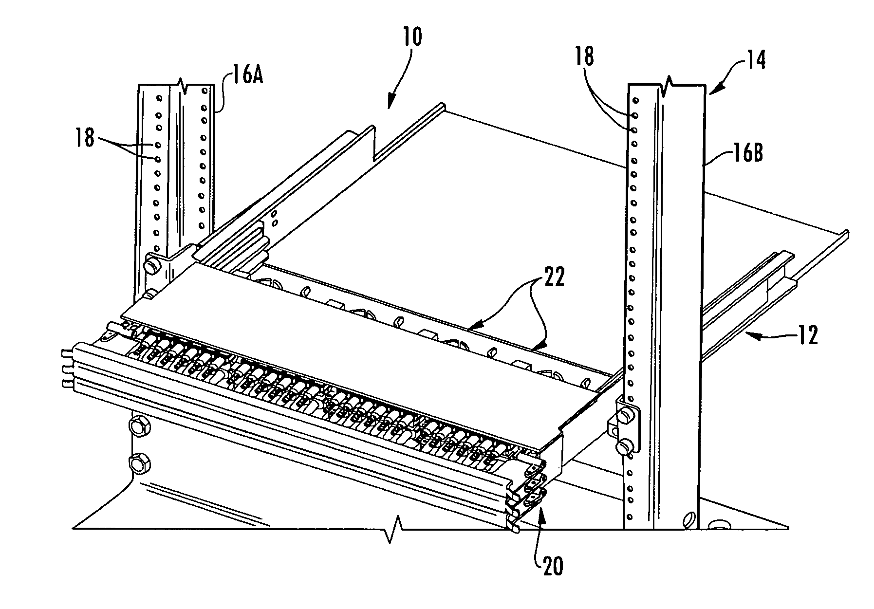
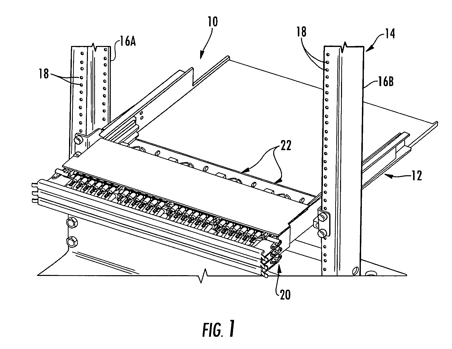
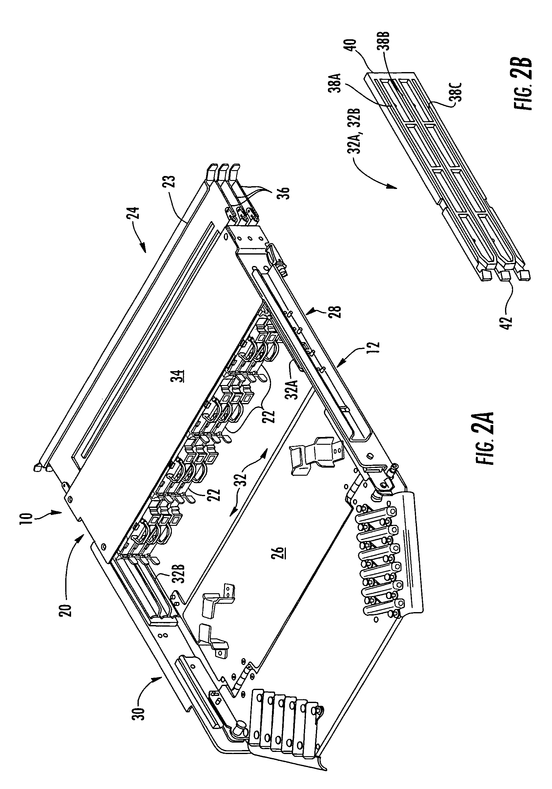
[0011]Embodiments disclosed in the detailed description include fiber optic equipment that supports one or more rear-installable fiber optic modules. The fiber optic modules are configured to support fiber optic connections. The fiber optic equipment is comprised of a chassis defining a front end and a rear section. At least one guide system is disposed in the chassis and configured to receive at least one fiber optic module. The guide system may be provided in the form of a rail guide system. The guide system receives a fiber optic module from the rear section of the chassis and is configured to guide the fiber optic module toward the front end of the chassis. In this manner, a technician can make fiber optic connections to fiber optic modules and also install the fiber optic modules into the fiber optic equipment from the rear section of the chassis to reduce time and / or labor in making fiber optic connections.
[0012]In some disclosed embodiments, the guide system is comprised of a...
PUM
 Abstract
Description
Claims
Application Information