Electrode for electrochemical element, its manufacturing method, and electrochemical element using the same

a technology of electrochemical elements and electrochemical elements, applied in the field of electrochemical elements, can solve the problems of inability to realize the enhancement of battery capacity, inability to substantially improve the cycle characteristics, and the active material layer may be torn or peeled, so as to achieve high capacity, improve the charging and discharging cycle characteristics, and high safety

Inactive Publication Date: 2012-05-29
PANASONIC CORP
View PDF15 Cites 1 Cited by
  • Summary
  • Abstract
  • Description
  • Claims
  • Application Information

AI Technical Summary

Benefits of technology

[0016]Accordingly, near the interface of the current collector, expansion and contraction due to insertion and extraction of lithium ions of the columnar body can be suppressed, and a high capacity is realized, and an electrode substantially improved in the charging and discharging cycle characteristics may be obtained. Since the columnar body is disposed discretely on the convex portions of the current collector, mutual contact of columnar bodies due to expansion of the leading end of columnar body may be alleviated, and crease of the current collector and peeling of columnar bodies from the current collector may be prevented. The space formed among the columnar bodies can insert and extract lithium entirely around the columnar bodies, and the move of the electrolytic solution is hardly disturbed. As a result, an electrode excellent in high-rate discharging and low temperature characteristics may be realized.
[0018]Accordingly, near the interface of the current collector, expansion and contraction due to insertion and extraction of lithium ions of the columnar bodies can be suppressed, and a high capacity is realized, and an electrode substantially improved in the charging and discharging cycle characteristics may be obtained.
[0019]The electrochemical element of the present invention has the electrode for electrochemical element described above, a counter electrode capable of inserting and extracting lithium ions reversibly, and a non-aqueous electrolyte. Hence, an electrochemical element high in safety and excellent in reliability is manufactured.

Problems solved by technology

As a result, as compared with the case of forming on the entire surface, the effect is suppressed, but a stress similarly occurs at the interface of columnar thin film and current collector, and peeling may occur, and substantial improvement of cycle characteristics is not expected.
Therefore, both prevention of peeling of columnar thin film from the current collector or creasing of current collector and enhancement of battery capacity cannot be realized at the same time.
The leading end of the active material layer may be expanded, but the active material layer near the interface of the current collector is hardly expanded, and along with the progress of charging and discharging cycles, the active material layer may be torn or peeled.
In particular, when the active material layer is increased in thickness, this effect becomes more obvious, and there is a problem for enhancement of capacity.

Method used


Image

  • Electrode for electrochemical element, its manufacturing method, and electrochemical element using the same
  • Electrode for electrochemical element, its manufacturing method, and electrochemical element using the same
  • Electrode for electrochemical element, its manufacturing method, and electrochemical element using the same

Examples


first exemplary embodiment

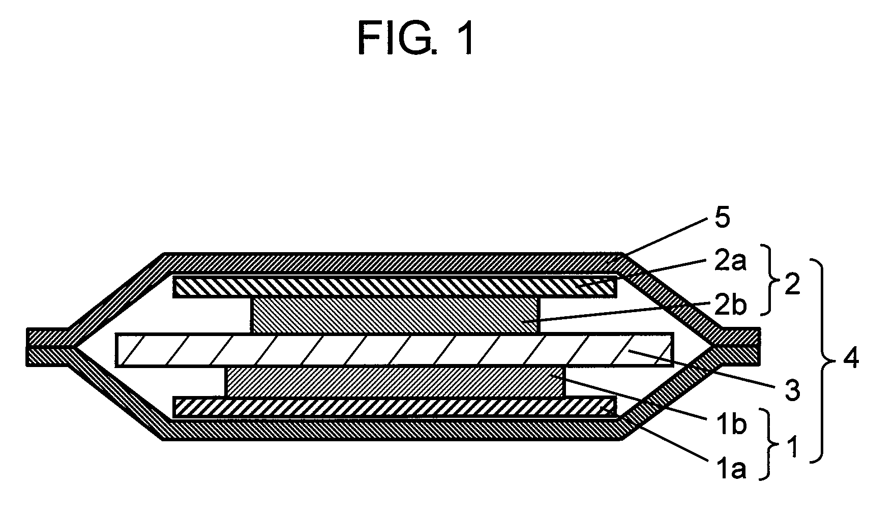
[0039]FIG. 1 is a sectional view of a non-aqueous electrolyte secondary battery in a first exemplary embodiment of the present invention.

[0040]As shown in FIG. 1, a laminated type non-aqueous electrolyte secondary battery (or merely battery) includes electrode group 4 having negative electrode 1 specifically described below, positive electrode 2 opposite to negative electrode 1 for reducing lithium ions in discharging process, and porous separator 3 interposed between them for preventing direct contact of negative electrode 1 and positive electrode 2. Electrode group 4 and an electrolyte (not shown) having lithium ion conductivity are accommodated in outer case 5. The electrolyte having lithium ion conductivity is impregnated in separator 3. One end of positive electrode lead (not shown) and negative electrode lead (not shown) is connected respectively to positive electrode current collector 2a and negative electrode current collector 1a, and other end is drawn out to outside of out...

second exemplary embodiment

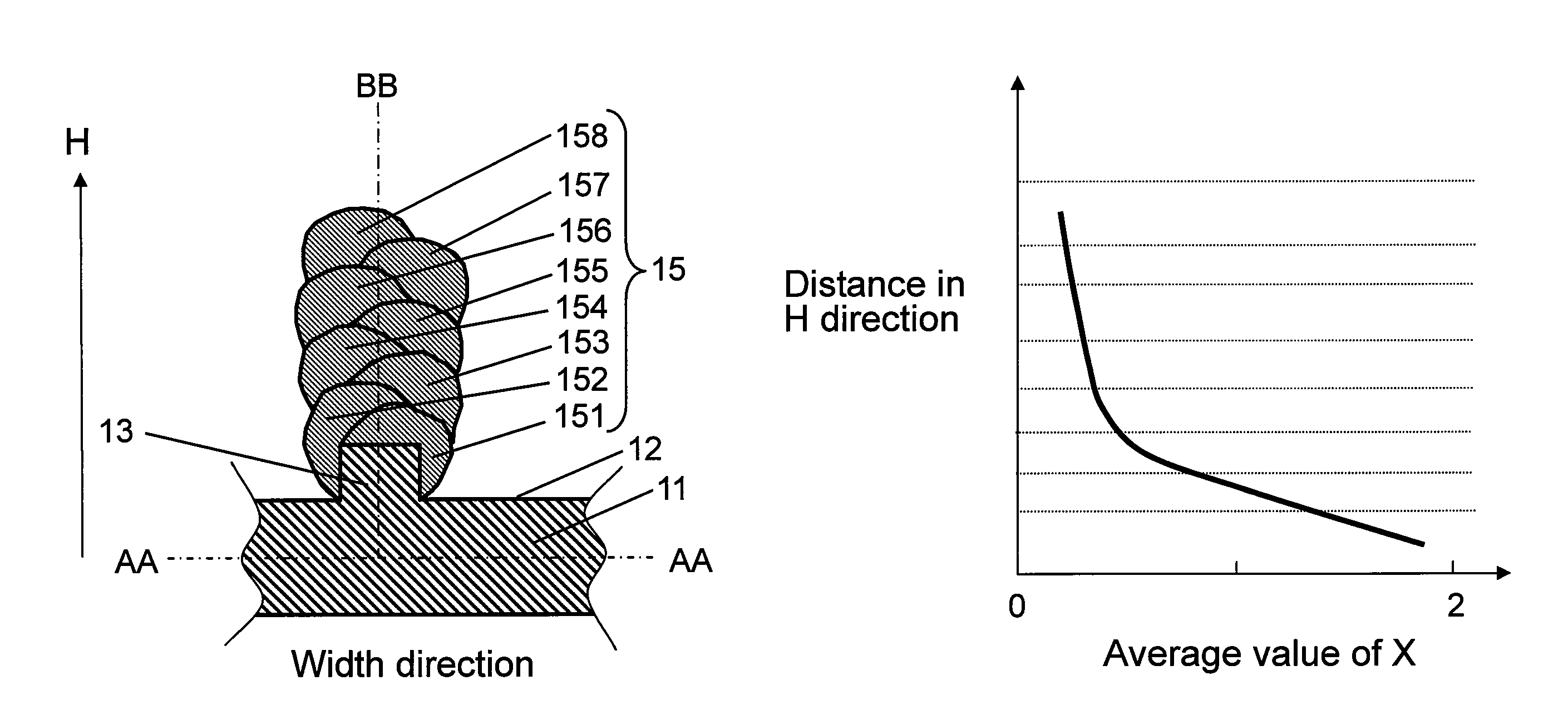
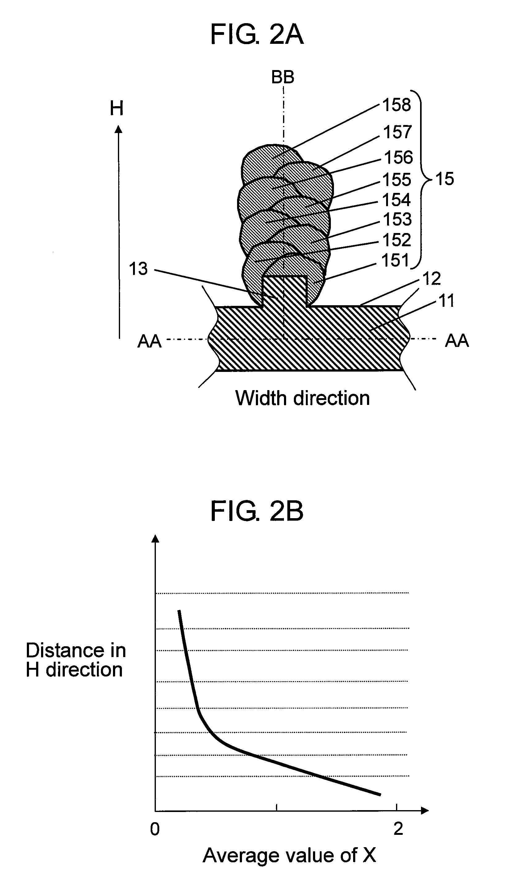
[0086]In a second exemplary embodiment of the present invention, a negative electrode is described by referring to FIG. 6A and FIG. 6B.

[0087]FIG. 6A is a partial sectional schematic diagram of structure of a negative electrode25 in the second exemplary embodiment of the present invention, and FIG. 6B is a schematic diagram explaining changes of a value of x in H direction of columnar bodies 25a in the exemplary embodiment. In FIG. 6B, changes of the values of x on line BB in FIG. 6A are shown.

[0088]Second exemplary embodiment differs from negative electrode 1 in the first exemplary embodiment in that one columnar body 25a is provided in perpendicular direction on convex portion 13 of current collector 11. Other elements of the battery are same, and same elements are identified with same reference numerals in the following explanation.

[0089]That is, as shown in FIG. 6A, concave portion 12 and convex portion 13 are provided at least on upper surface of current collector 11 made of con...

third exemplary embodiment

[0103]A negative electrode in a third exemplary embodiment of the present invention is described below by referring to FIG. 8A and FIG. 8B.

[0104]FIG. 8A is a partial sectional schematic diagram of structure of negative electrode 35 in the third exemplary embodiment of the present invention, and FIG. 8B is a schematic diagram explaining changes of a value of x in H direction of columnar body 35a in the exemplary embodiment. In FIG. 8B, changes of the value of x on line A-A in FIG. 8A are shown.

[0105]Third exemplary embodiment is different from negative electrode 25 of the second exemplary embodiment in that one columnar body 35a is formed obliquely on convex portion 13 of current collector 11. Basically, the columnar body portion of first stage in the first exemplary embodiment is formed largely as one columnar body. The other structure of the battery is same, and same components are identified with same reference numerals in the following explanation. The manufacturing apparatus is ...


PUM

PropertyMeasurementUnit
widthaaaaaaaaaa
widthaaaaaaaaaa
heightaaaaaaaaaa

Abstract

Having a current collector having a concave portion and a convex portion at least on one side, and a columnar body formed on the convex portion of the current collector, the columnar body contains an active material for inserting and extracting lithium ions bonding at least with oxygen, and the oxygen content ratio of the active material of the columnar body becomes smaller as going away from the interface of the current collector.

Description

RELATED APPLICATIONS[0001]This application is the U.S. National Phase under 35 U.S.C. §371 of International Application No. PCT / JP2008 / 000394, filed on Feb. 29, 2008, which in turn claims the benefit of Japanese Application No. 2007-116932, filed on Apr. 26, 2007, the disclosures of which Applications are incorporated by reference herein.TECHNICAL FIELD[0002]The invention relates to an electrochemical element excellent in charging and discharging characteristics, and more particularly to an electrode for electrochemical element excellent in capacity retaining rate, its manufacturing method, and an electrochemical element using the same.BACKGROUND ART[0003]Recently, as an electrochemical element, a lithium ion secondary battery represented by non-aqueous electrolyte secondary battery is widely used because it is light in weight, high in electromotive force, and high in energy density. For example, the demand for lithium secondary battery is increasing for use as driving power source ...

Claims


Application Information

Patent Timeline
Patent Type & Authority Patents(United States)
IPC IPC(8): H01M4/76H01M4/13B05D5/12H01M4/58H01G9/00H01G11/06H01G11/22H01G11/30H01G11/66H01G11/70H01G11/86H01M4/131H01M4/1391H01M4/1395H01M4/36H01M4/48H01M4/64
CPCH01G9/016H01G11/26H01G11/28H01G11/50H01G11/70H01G11/86H01M4/134H01M4/1395H01M4/366H01M4/70H01G9/058Y10T156/10H01M10/052H01M2004/021Y02E60/122Y02E60/13Y02E60/10H01G11/74H01G11/22H01M4/02H01M4/04H01M10/05
Inventor UGAJI, MASAYAOHARA, KEISUKEWATANABE, KAZUHIRO
Owner PANASONIC CORP
Why Eureka
Try Eureka