Punch-down device

a technology of punching device and terminal seat, which is applied in the direction of coupling device connection, unstripped conductor connection apparatus, manufacturing tools, etc., can solve the problems of increasing costs, consuming time, and a large number of insertion slots of terminal seats, and achieves increased punching operation efficiency, effective positioning, and convenient operation.

Inactive Publication Date: 2012-06-05
LIANG YU TAI
View PDF5 Cites 5 Cited by
  • Summary
  • Abstract
  • Description
  • Claims
  • Application Information

AI Technical Summary

Benefits of technology

[0007]Another objective of the present invention is to provide a punch-down device that simultaneously cuts off excessive length of conductor to thereby make the operation easy and realize effective positioning.
[0008]To achieve the above objectives, the present invention provides a punch-down device, which comprises: a housing, which forms therein hollow channels; a driving mechanism, which comprises a rotation shaft and at least one rotary wheel, which is connected and supported by the rotation shaft at a top portion of the housing, the rotation shaft having an end extending outside the housing to form a coupling section, each of the rotary wheels having a surface forming two tracks and two pegs, the two pegs of one rotary wheel being received in the two tracks of an adjacent one of the rotary wheels; and at least one punch-down member, which is received in the hollow channels to correspond to the rotary wheels and be driven to move by the rotary wheels, the punch-down member having lower ends forming conductor depression sections. As such, the punch-down device carries out an operation of punching down and depressing conductors, whereby the efficiency of punch-down operation is increased and the operation is easy and reliable positioning is achieved.

Problems solved by technology

However, the number of the insertion slots of the terminal seats is great.
This consumes time and increases the costs.
Further, the insertion slot of the terminal seat has a narrow opening, making it hard to precisely fit the conductor into the insertion slot, which leads to repeated punch-down operation and the punch-down operation may not be effective and reliable.
Further, improper application force occurring in the punch-down operation may cause damage of the structure of an opposite end of the metal terminal.

Method used


Image

  • Punch-down device
  • Punch-down device
  • Punch-down device

Examples


Embodiment Construction

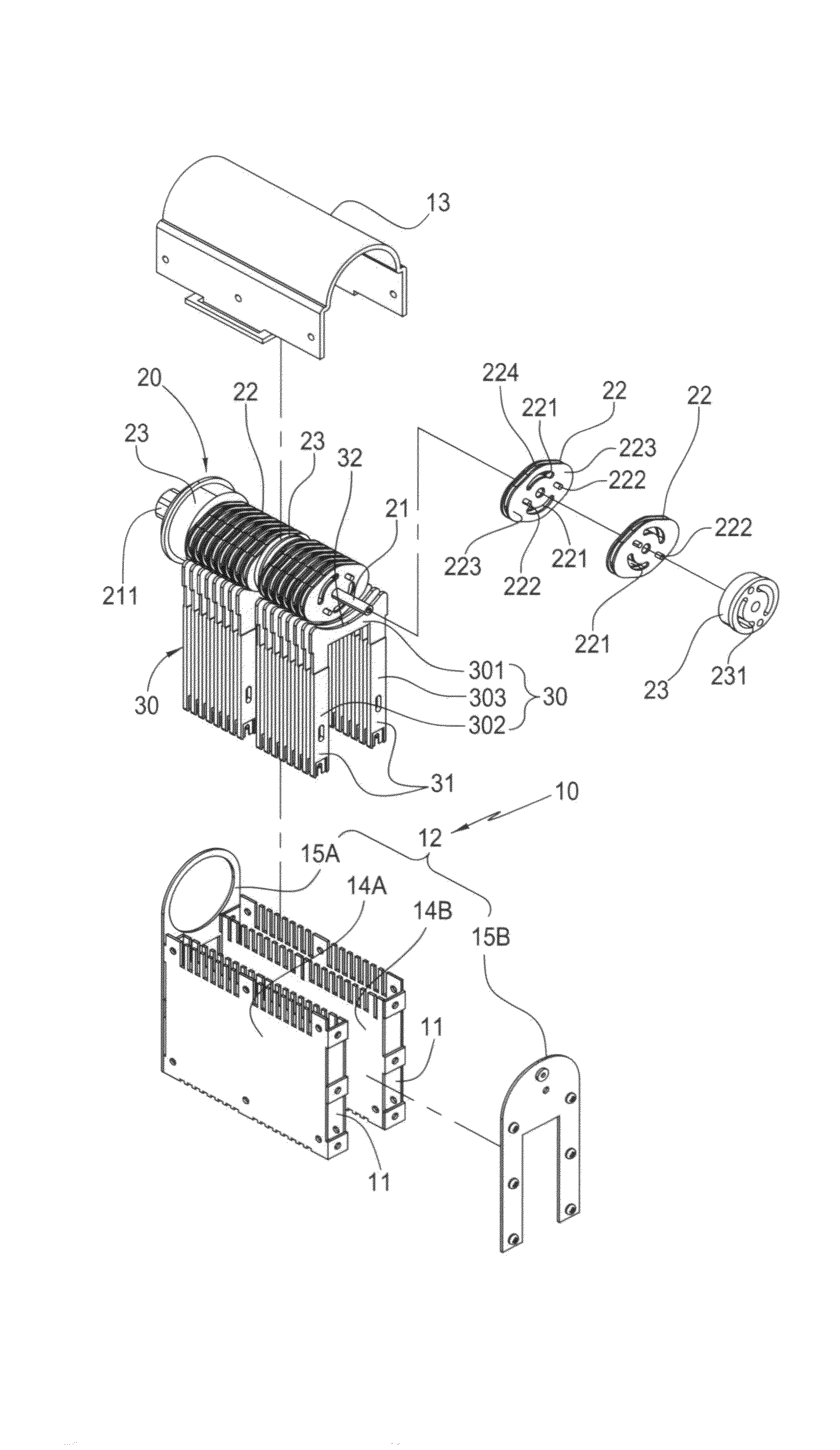
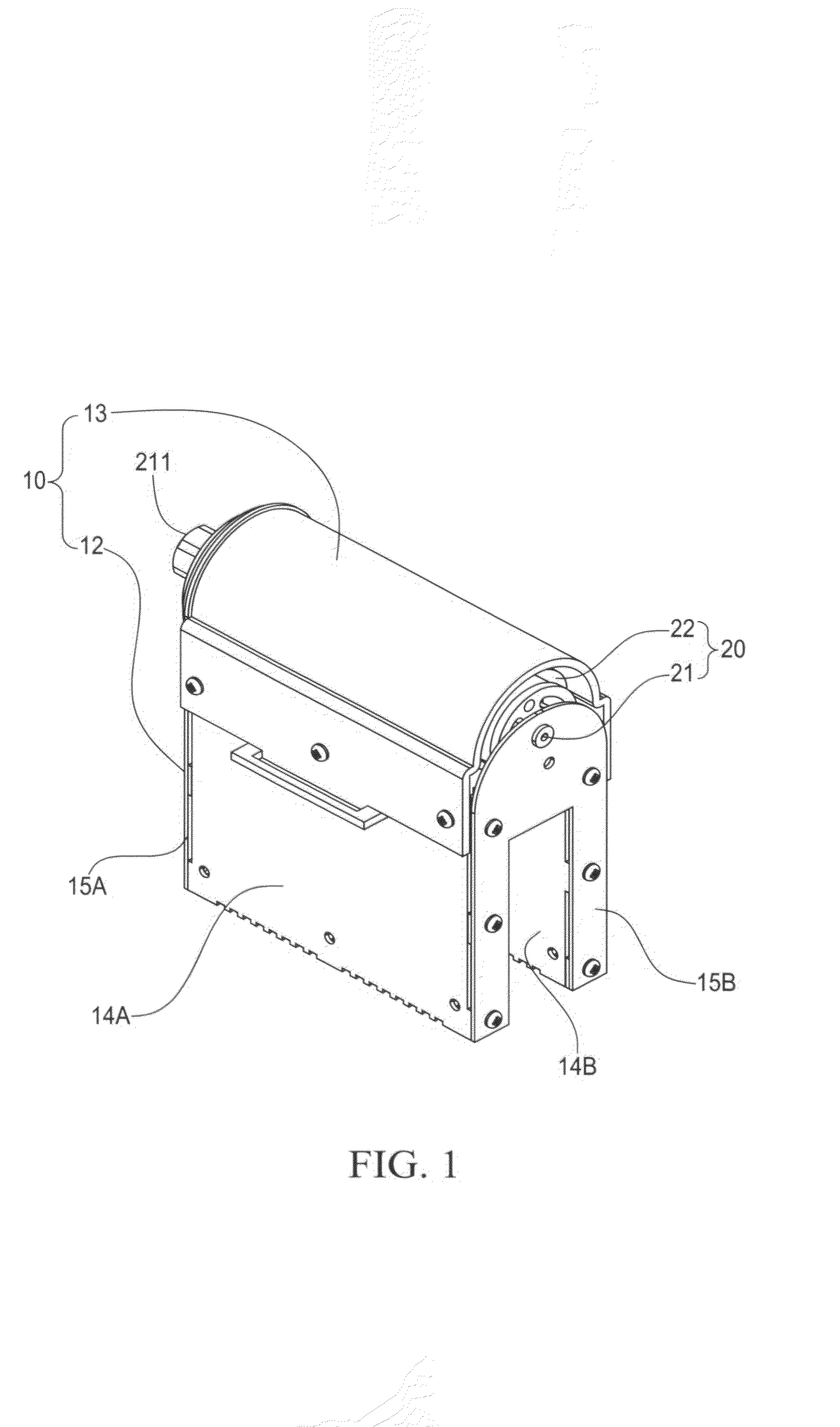
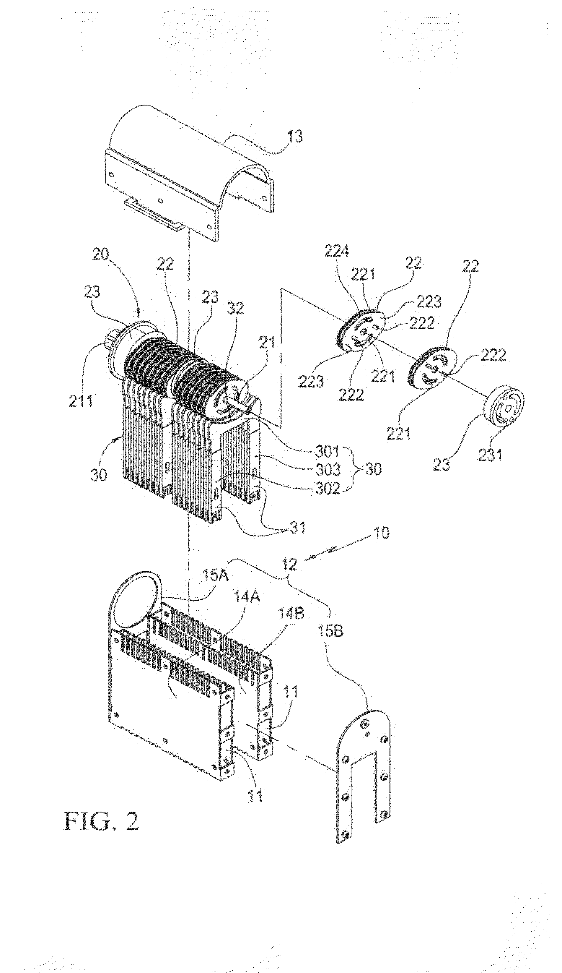
[0018]With reference to the drawings and in particular to FIGS. 1-4, the present invention provides a punch-down device, which comprises a housing 10, a driving mechanism 20, and at least one punch-down member 30 (multiple punch-down members being visible in the drawings).

[0019]The housing 10 forms therein hollow channels 11. The driving mechanism 20 comprises a rotation shaft 21 and at least one rotary wheel 22 (multiple rotary wheels being visible in the drawings). The rotary wheels 22 are connected in cascade to the rotation shaft 21 and arranged in a top portion of the housing 10. The rotation shaft 21 has an end extending outside the housing 10 to form a coupling section 211. Each rotary wheel 22 has a surface forming two tracks 221 and two pegs 222, so that the two pegs 222 of the rotary wheel 22 are received in the two tracks defined in an adjacent rotary wheel 22. The punch-down members 30 are movably received in the hollow channels 11 to correspond in position to the rotary...


PUM

PropertyMeasurementUnit
timeaaaaaaaaaa
forceaaaaaaaaaa
lengthaaaaaaaaaa

Abstract

A punch-down device includes a housing, a driving mechanism, and at least one punch-down member. The housing forms therein hollow channels. The driving mechanism includes a rotation shaft and at least one rotary wheel, which is connected and supported by the rotation shaft at a top portion of the housing. The rotation shaft has an end extending outside the housing to form a coupling section. Each of the rotary wheels has a surface forming two tracks and two pegs. The two pegs of one rotary wheel are received in the two tracks of an adjacent one of the rotary wheels. The punch-down member is received in the hollow channels to correspond to the rotary wheels and be driven to move by the rotary wheels. The punch-down member has lower ends forming conductor depression sections. As such, the punch-down device carries out an operation of punching down and depressing conductors, whereby the efficiency of punch-down operation is increased and the operation is easy and reliable positioning is achieved.

Description

FIELD OF THE INVENTION[0001]The present invention relates to a punch-down device, which is applicable to an assembling operation of patch panel of an electronic apparatus to fit conductors of telecommunication cables arranged inside the electronic apparatus into terminal seats formed on the patch panel.BACKGROUND OF THE INVENTION[0002]A conventional telecommunication apparatus is often provided with a patch panel that forms two rows of multiple terminal seats along two side edges thereof, between which a channel is formed to receive the extension of telecommunication cables therethrough. Each terminal seat comprises a plurality of insertion slots each receiving and retaining therein a metal terminal electrically connected to the patch panel. Each telecommunication cable is associated with one terminal seat and each telecommunication cable comprises a plurality of internal conductors. The conductors are respectively associated with the insertion slots of the terminal seat to electric...

Claims


Application Information

Patent Timeline
Patent Type & Authority Patents(United States)
IPC IPC(8): H01R43/01
CPCH01R43/015H01R24/64Y10T29/53257Y10T29/53243Y10T29/5323Y10T29/53217Y10T29/53222Y10T29/53252
Inventor LIANG, YU-TAI
Owner LIANG YU TAI
Why Eureka
Try Eureka