Fabric gate

a fabric gate and gate body technology, applied in the field of safety gates, can solve the problem of inconvenient use of fabric gates

Active Publication Date: 2012-06-05
WANG TSUNG HSIANG
View PDF17 Cites 31 Cited by
  • Summary
  • Abstract
  • Description
  • Claims
  • Application Information

AI Technical Summary

Problems solved by technology

Therefore, the use of the conventional fabric gate is inconvenient.

Method used


Image

  • Fabric gate
  • Fabric gate
  • Fabric gate

Examples


Embodiment Construction

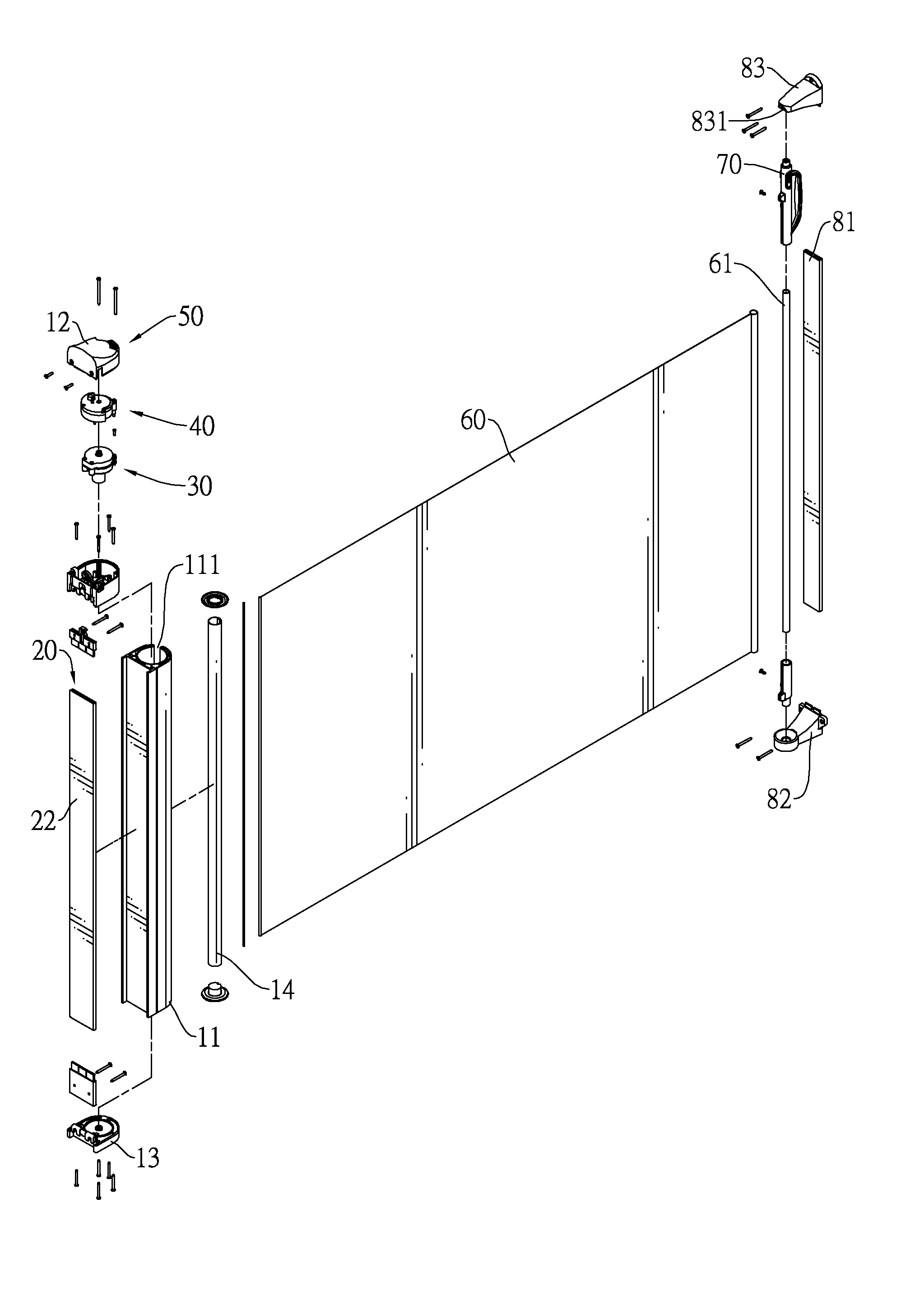
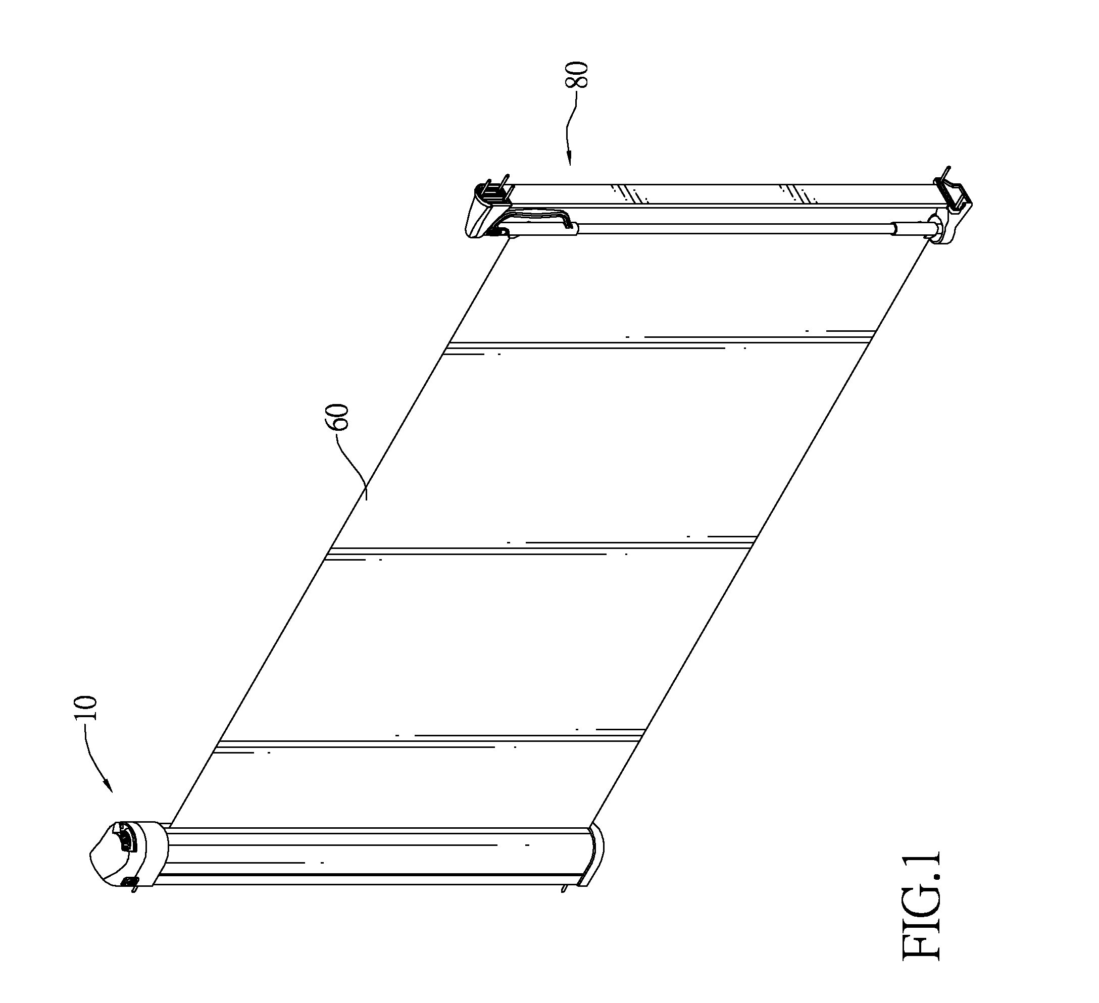
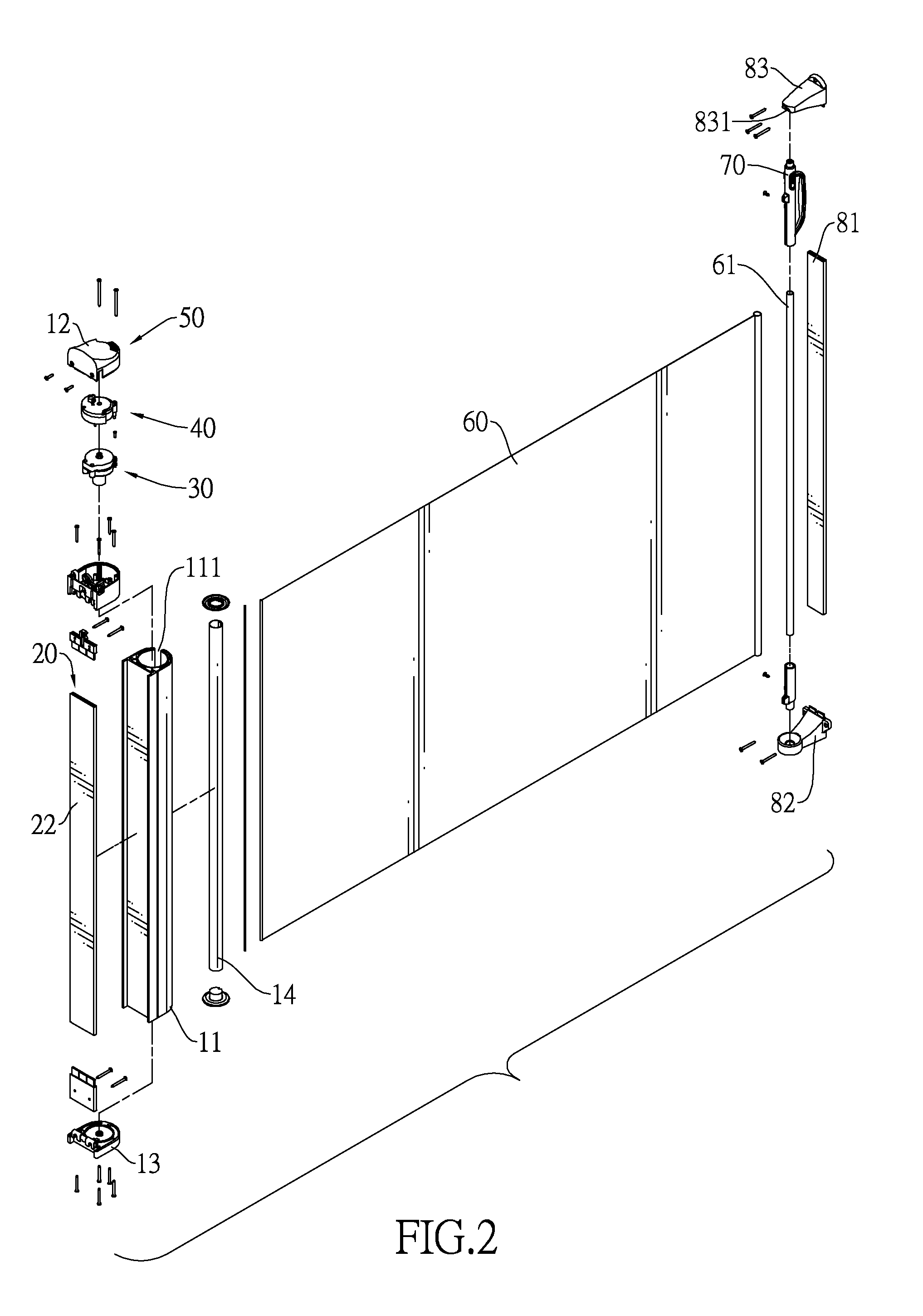
[0030]With reference to FIGS. 1, 2 and 8, a fabric gate in accordance with the present invention comprises a reeling column assembly (10), a ratchet assembly (30), a coil torsion spring (34), a delaying assembly (40), a driving device (50), an expandable fabric (60) and a connecting column assembly (80).

[0031]The reeling column assembly (10) comprises a hollow post (11), a to cap (12), a bottom cap (13), a reeling shaft (14) and a locking assembly (20). The hollow post (11) has a central hole, two ends, a top opening, a bottom opening and a fabric outlet (111). The central hole is defined through the post (11). The top opening and the bottom opening are defined respectively in two ends of the post (11) and communicate with the central hole. The fabric outlet (111) is defined longitudinally in the post (11) and communicates with the central hole.

[0032]The top cap (12) and the bottom cap (13) are attached respectively to the ends of the post (11) and close the top and bottom openings ...


PUM


Abstract

A fabric gate has a ratchet assembly, a delaying assembly and a driving device. The ratchet assembly has a ratchet, a positioning ring and a driven pad. The ratchet has a wheel provide with multiple upper ratchet teeth and multiple lower ratchet teeth. The upper ratchet teeth extend toward a direction opposite to that of the lower ratchet teeth extending. The positioning ring is expandable and has engaging teeth engaging respectively with the ratchet teeth on the ratchet. The driven pad is attached to the top of the positioning ring to expand the positioning ring when the driven pad is rotated by the driving device. The delaying assembly is mounted in the top cap and connected to the ratchet assembly to reduce to the rotating speed of the driven pad.

Description

BACKGROUND OF THE INVENTION[0001]1. Field of the Invention[0002]The present invention relates to a safety gate, and more particularly to a fabric gate for forming a safety zone for children or pets with an expandable fabric.[0003]2. Description of Related Art[0004]A safety gate is mounted in a room to form safety zone for children or pets to keep them from a dangerous location, such as kitchen. A conventional fabric gate comprises two securing columns and an expandable fabric. The securing columns are secured respectively on two walls and including a reeling column and a connecting column. The fabric is reeled in the reeling columns and is expended to connect to the connecting column and block the passage between the walls. A ratchet device is mounted in the reeling column to keep the fabric from being retracted and reeled into the reeling column unintentionally. To reel the fabric into the reeling column, the fabric has to be disconnected from the connecting column and pulled outwa...

Claims


Application Information

Patent Timeline
Patent Type & Authority Patents(United States)
IPC IPC(8): E06B9/56
CPCE06B9/0692E06B9/40E06B2009/002
Inventor WANG, TSUNG-HSIANG
Owner WANG TSUNG HSIANG
Why Eureka
Try Eureka