
Image forming apparatus

a technology of image forming and forming tubes, which is applied in the direction of digitally marking record carriers, visual presentation using printers, instruments, etc., can solve the problems of insufficient accuracy of correction performed, shifted recording positions,

Inactive Publication Date: 2012-06-05
RICOH KK
View PDF7 Cites 3 Cited by
  • Summary
  • Abstract
  • Description
  • Claims
  • Application Information

AI Technical Summary

Benefits of technology

[0011]The present invention is made in light of the above problem and may provide an image forming apparatus capable of controlling (reducing) the shift amount of the recording positions by detecting a positional shift amount not only in the main-scanning direction and but also in the sub-scanning direction and an inclination amount (angle) of the recording head both of the forward scanning and the backward scanning by making a simple and easy addition to the configuration.
[0014]According to an embodiment of the present invention, the positional shift amount of the dot images formed in a forward scanning of the recording head, the positional shift amount of the dot images formed in a backward scanning of the recording head, the inclination amount of the recording head in the forward scanning, and the inclination amount of the recording head in the backward scanning are obtained based on calibration image data obtained by imaging two first marks and two second marks in a single view by the imaging unit, the two first marks being a predetermined pattern formed while the recording head is moved in a forward direction, the two second marks being a predetermined pattern formed while the recording head is moved in a backward direction. Therefore, it may become possible to adequately control the recorded positional shift amounts.

Problems solved by technology

However, there may arise a problem that when an image is formed by scanning in both forward and backward directions in the main-scanning direction (i.e., in bi-directional printing), the recorded positions may be shifted (displaced) due to the shifted positions between the dots formed in the forward scanning and the dots formed in the backward scanning.
Therefore, the correction performed may not be accurate enough.

Method used


Image

  • Image forming apparatus
  • Image forming apparatus
  • Image forming apparatus

Examples


Embodiment Construction

[0035]In the following, a configuration of an image forming apparatus according to an embodiment of the present invention is described.

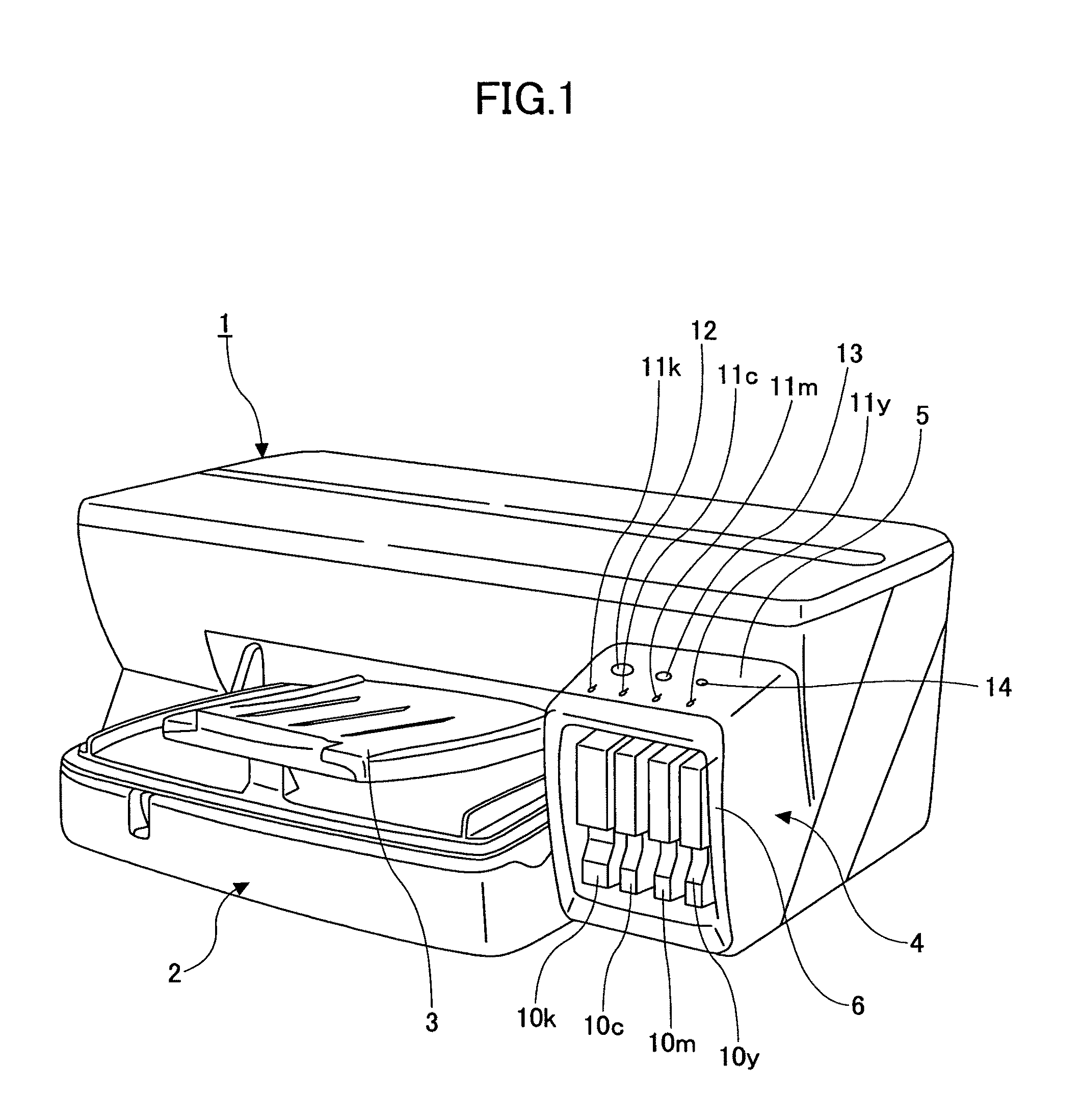
[0036]FIG. 1 is a front oblique view of an inkjet recording apparatus as an image forming apparatus according to an embodiment of the present invention.

[0037]As shown in FIG. 1, the inkjet recording apparatus includes an apparatus main body 1, a sheet tray 2 to be loaded into the apparatus main body 1 for stacking and providing sheets, and a discharge tray 3 detachably provided to the apparatus main body 1 for stacking discharged sheets on which images are recorded (formed). The inkjet recording apparatus further includes a cartridge loading section 4 protruding from the front of the apparatus main body 1 on one side (the side other than the side where the sheet tray 2 and the discharge tray 3 are provided) and an operations / display section 5 provided on the upper surface of the cartridge loading section 4 and providing operation buttons and a displa...


PUM


Abstract

An image forming apparatus is disclosed that includes a recording head having a plurality of nozzles and scanning in forward and backward scanning directions to form dot images on the recording medium, an imaging unit imaging an image on the recording medium, a detection unit detecting a positional shift amounts of the dot images and inclination amounts of the recording head based on calibration image data obtained by imaging two first marks and two second marks in a single view by the imaging unit, and a correction unit correcting a drive of the recording head based on the detected positional shift amounts and the inclination amounts of the recording head.

Description

CROSS-REFERENCE TO RELATED APPLICATIONS[0001]The present application claims priority under 35 U.S.C §119 to Japanese Patent Application Publication No. 2008-162792 filed Jun. 23, 2008, the entire contents of which are hereby incorporated herein by reference.BACKGROUND OF THE INVENTION[0002]1. Field of the Invention[0003]The present invention generally relates to an image forming apparatus such as an inkjet recording apparatus, and more particularly to a technique of correcting a recording position of image data in an image forming apparatus having the recording head capable of performing bi-directional scanning in the main-scanning direction to form the image data.[0004]2. Description of the Related Art[0005]Generally, there has been known an image forming apparatus having its image forming section employing an electrophotographic image forming method such as a printer, a facsimile machine, a copier, or a multifunction peripheral having such functions. Some image forming apparatuses...

Claims


Application Information

Patent Timeline
Patent Type & Authority Patents(United States)
IPC IPC(8): B41J29/393
CPCB41J29/38B41J29/393G06K15/102B41J2/2135
Inventor TAKAHASHI, HIROSHIKOBAYASHI, MASATOKIMURA, TOMONORITAKEI, KAZUSHISAKURADA, YUICHISATOH, NOBUYUKISAKURAI, YASUO
Owner RICOH KK
Learn More