Reinforced extrusion and method for making same

a technology of reinforced extrusion and extrusion method, which is applied in the direction of transportation and packaging, other domestic articles, coatings, etc., can solve the problems of increased metal requirements for pre-formed metal cores, increased metal requirements, and increased costs of pre-formed metal cores

Active Publication Date: 2012-06-05
M&S EXTRUSIONS INC DBA VINTECH IND
View PDF3 Cites 4 Cited by
  • Summary
  • Abstract
  • Description
  • Claims
  • Application Information

AI Technical Summary

Benefits of technology

[0005]The present invention is directed to a reinforced extrusion for attaching to a motor vehicle component edge or flange for helping to seal and trim a door, retractable window, trunk, and the like. The reinforced extrusion includes a reinforcement core comprising at least one operably flexible wire arrangement formed as a series of loops spaced apart and a plurality of threaded cords attached therewith, e.g., forming a snake skin or webbing like configuration. A thermoplastic overmold having a predetermined durometer and thickness is formed on at least one side of the reinforcement core, e.g., formed on one side while the reinforcement core is substantially flat. An extruded layer having a predetermined durometer and thickness is selectively formed around the thermoplastic overmold and reinforcement core. The thermoplastic overmold helps to prevent the reinforcement core pattern from showing through to an outside show surface of the extruded layer when installed on the motor vehicle. A channel portion that is semi-rigid for retaining a motor vehicle component edge or flange, e.g., a door frame flange is formed by operably bending or shaping the reinforcement core with thermoplastic overmold to a predetermined shape, e.g., forming a predetermined shape during an extrusion process. The extruded layer also has a flange portion that is at least partly flexible and operably shaped to extend generally from the channel portion and engage a motor vehicle component, e.g., a window pane, to help trim and / or seal.

Problems solved by technology

In such known extrusion trims, the undesirable hungry horse appearance becomes even more pronounced when the extrusion trims are bent and manipulated into the installed position in the vehicle.
Another common problem with known extrusion trims is that the pre-formed metal cores can require larger amounts of metal which can be an added expense.

Method used


Image

  • Reinforced extrusion and method for making same
  • Reinforced extrusion and method for making same
  • Reinforced extrusion and method for making same

Examples


Embodiment Construction

[0017]The following description of the preferred embodiment(s) is merely exemplary in nature and is in no way intended to limit the invention, its application, or uses.

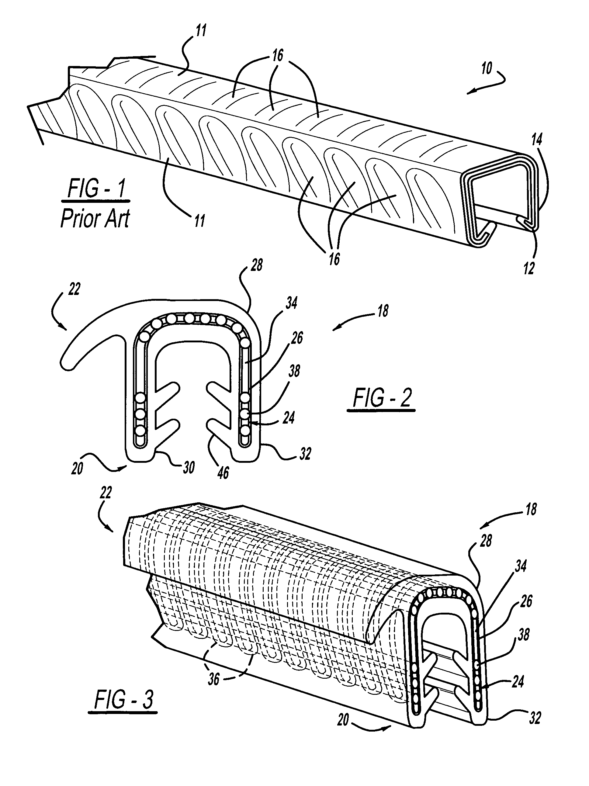
[0018]Referring to FIG. 1, there is shown an example of a prior art extrusion trim 10 depicting an example of an undesirable rippled appearance or hungry horse effect on the visible show surfaces 11. The extrusion trim 10 has a pre-formed metal core 12 and an elastomeric material 14 extruded directly about the metal core 12. The indentations 16 or recesses giving a hungry horse appearance is caused by the elastomeric material 14 sinking into slots or apertures between metal members of the metal core 12 when the elastomeric material 14 is extruded about the metal core 12.

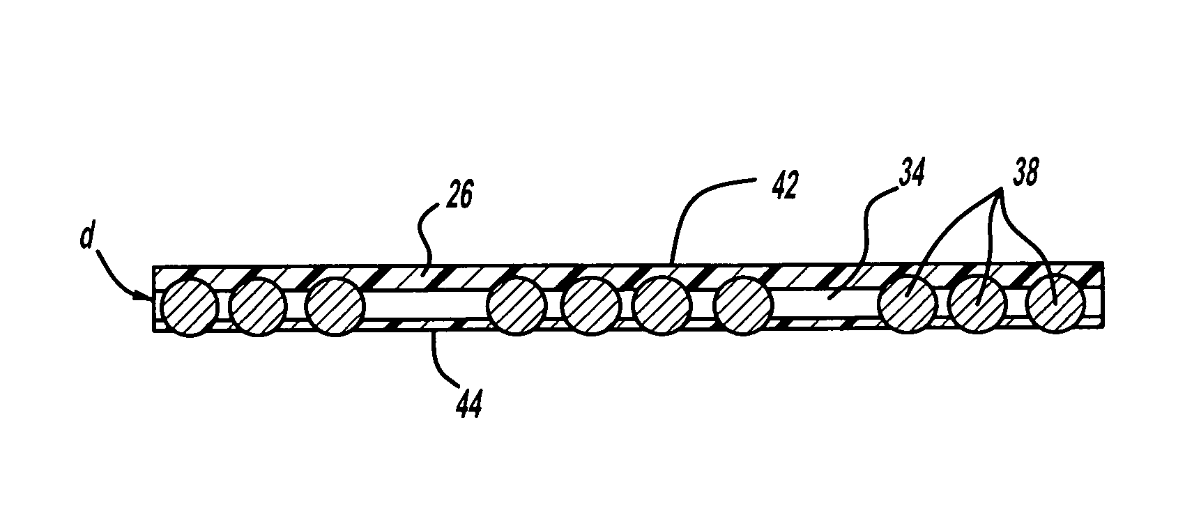
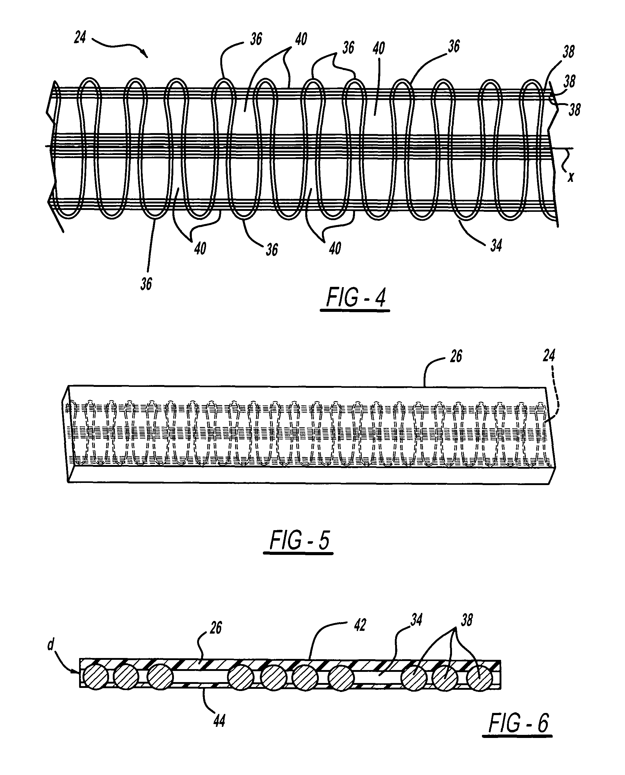
[0019]Referring to FIGS. 2-3, a reinforced extrusion of the present invention, generally shown at 18, includes a channel portion 20 that is semi-rigid, and a flange portion 22 that can be at least partly flexible and extends radially from the channel p...


PUM

PropertyMeasurementUnit
flexibleaaaaaaaaaa
thicknessaaaaaaaaaa
shapeaaaaaaaaaa

Abstract

A reinforced extrusion for attachment to a motor vehicle component edge or flange. The reinforced extrusion includes a reinforcement core having at least one flexible wire and at least one threaded cord. A thermoplastic overmold is formed on at least one side of the reinforcement core and at least partly fills any gaps formed in the reinforcement core. An extruded layer is selectively formed around the thermoplastic overmold and reinforcement core and has a flange extending flange portion extending from a channel portion for engaging a motor vehicle component. The thermoplastic overmold helps prevent the reinforcement core from showing through to any visible show surface of the reinforced extrusion.

Description

CROSS-REFERENCE TO RELATED APPLICATIONS[0001]This application claims the benefit of U.S. Provisional Patent Application No. 61 / 196,654, filed Oct. 20, 2008, the contents of which are incorporated by reference in their entirety.FIELD OF THE INVENTION[0002]The present invention relates to a reinforced extrusion, more specifically, to a reinforced extrusion for attachment to a motor vehicle and a method for making same.BACKGROUND OF THE INVENTION[0003]Extrusion trims are generally known and are commonly used for vehicle window, trunk, and door sealing and trimming. Typical extrusion trims have a hollow cavity for attachment to a flange on a vehicle and at least a portion of the extrusion trim is visible when installed into the vehicle. Typically, the extrusion trim comprises a pre-formed metal core or stamped metal plate configured to form the hollow cavity an elastomeric material extruded about the pre-formed metal core. The pre-formed metal core comprises metal members and slots or a...

Claims


Application Information

Patent Timeline
Patent Type & Authority Patents(United States)
IPC IPC(8): B32B3/08B29C48/154B29C48/08
CPCB29C47/0021B29C47/025B29K2021/00Y10T428/2495Y10T428/24521Y10T428/24198Y10T428/24983B29L2031/305B29C48/08B29C48/154
Inventor SCHOONOVER, JAMESMCNISH, VINCE
Owner M&S EXTRUSIONS INC DBA VINTECH IND
Why Eureka
Try Eureka